Lit. No. B64090, Rev. 00 23 April 1, 2006
ELECTRICAL INSTALLATION – VEHICLE SIDE
7. Remove the front signal light assembly from both
sides of the vehicle. On the driver side, feed the
violet (turn light) and gray (run light) wires from the
main lighting harness through the opening in the
signal light housing. Use a test light or ohm meter
to determine the proper wires in the vehicle’s
electrical system to splice into. Position one end of
the turn or run light wire into the splice lock
connector, and attach the vehicle wire into the
opposite side. Complete the splice by pinching
both wires together and locking the connector.
Repeat the splice procedure for the remaining
wire.
8. Repeat Step 7 for passenger side using the pink
(turn light) and gray (run light) wires.
9. Connect the vehicle headlights to the main lighting
harness using a light conversion harness kit. Due
to differences in the construction of the kits, and
the various make and model vehicles BLIZZARD
®
snowplows are installed on, a light conversion kit
is not packaged with your snowplow. Contact your
local BLIZZARD dealer to obtain the appropriate
conversion harness kit for your vehicle.
10. Secure the braided harness to the vehicle. Safely
route all harnesses around the engine
components and attach them to the vehicle with
cable ties. Extend the plow headlight connectors,
from the main lighting harness, through the grille
of the vehicle and position the harness power plug
and weather cap near the bumper. Cable tie the
plug to the vehicle bumper or tow hook to keep the
harness from hanging too low.
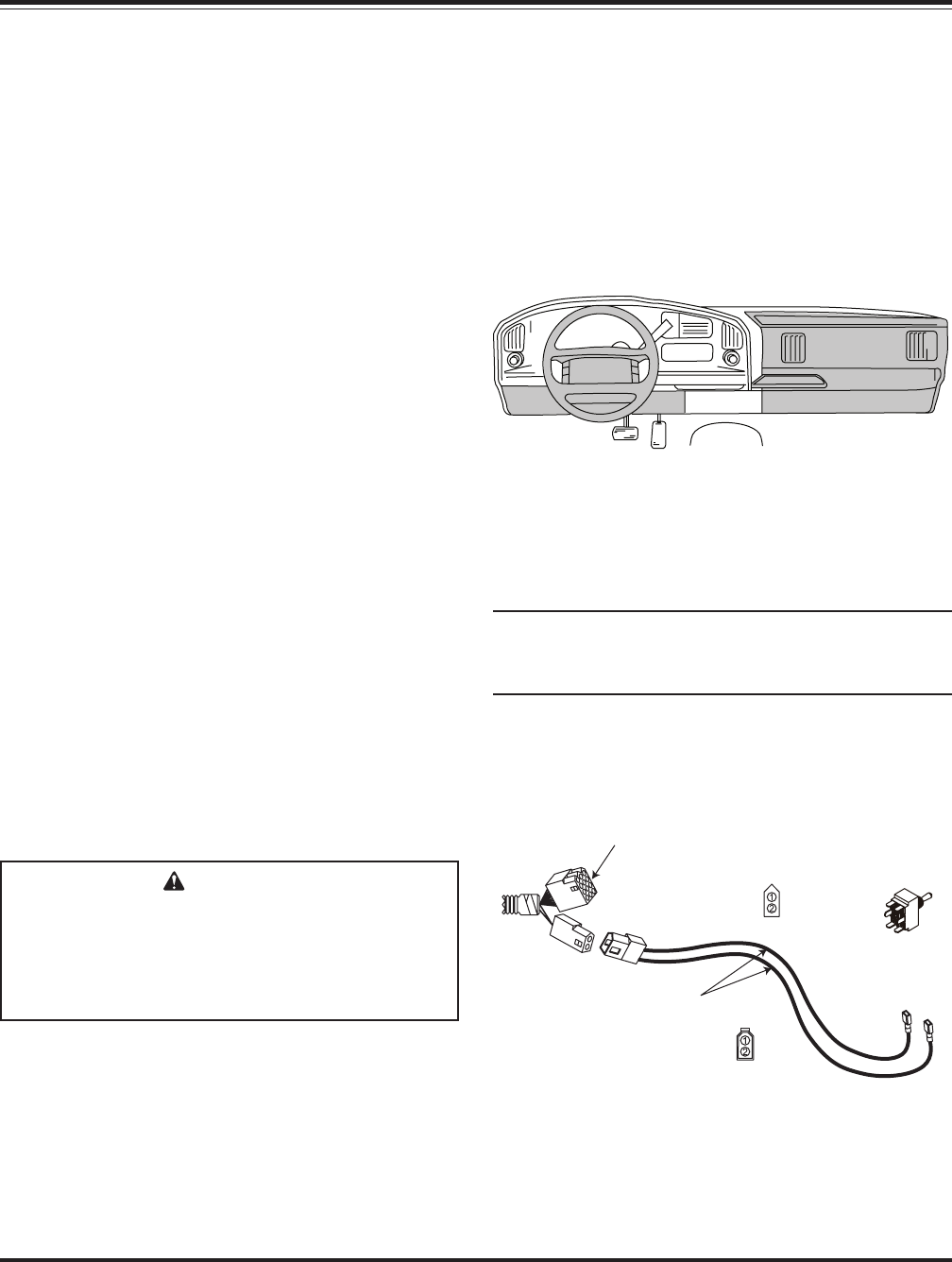
11. Install the remainder of the vehicle wire harness to
the interior of the cab. Find an accessible location
for the plow headlight toggle switch and bracket
under the dashboard. When choosing a location
for your switch, it should be mounted in easy
reach of the vehicle operator and not restricting
access to vehicle controls or vehicle
instrumentation. Do not mount the switch in areas
prohibited by the vehicle manufacturer for crash
worthiness. See the vehicle's body builders book,
owner's manual or service manual for details. The
shaded areas in the illustration below show the
most commonly restricted areas.
Install the headlight bracket using two self-drilling
screws. Insert the toggle switch through the
bracket and secure it with the hardware provided.
Plug both of the switch leads into the toggle
switch.
NOTE: Both terminals should be inserted into the
spades on the same side of the switch. One
terminal should be positioned in the middle spade.
Plug both 2-pin connectors together and this will
connect the toggle switch to the vehicle wire
harness. See illustration below.
Vehicle
Harness
Green/Yellow
12" Long
To Control
DPDT
Toggle
Switch
.250
Receptacles
END VIEW
(looking at connector)
END VIEW
(looking at connector)
CAUTION
Do not alter, modify or install additional
components in shaded areas of the following
illustration. Failure to comply may interfere
with air bag deployment or cause injury to
operator in an accident.


