


April 1, 2006 12 Lit. No. B64090, Rev. 00
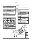
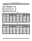
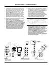
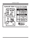
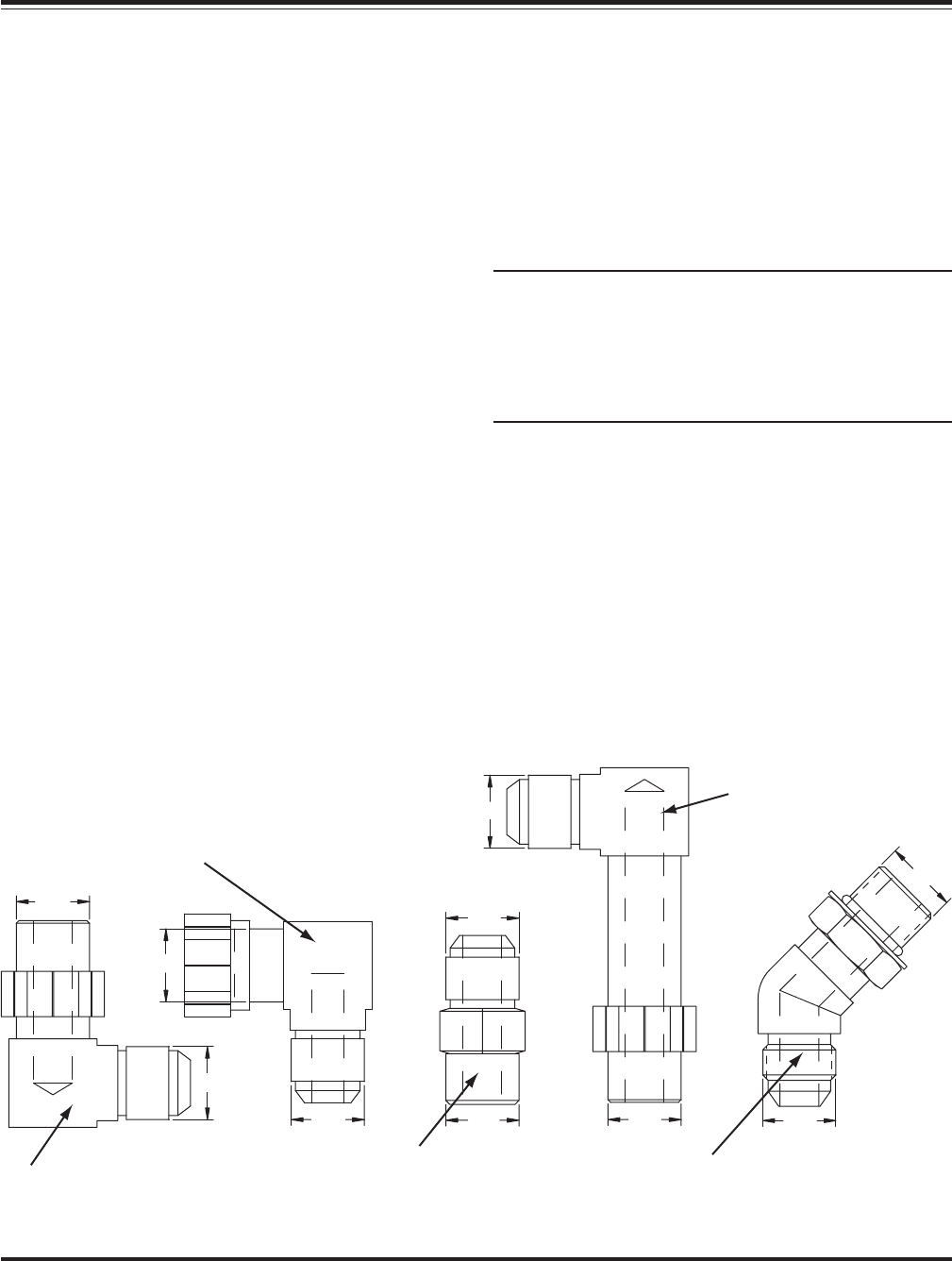
B60007
- Manifold Ports #3 & 4
- Lift Cylinder Rod End
9/16
9/16
B60005
- Manifold Port #1
- Angle Cylinders
9/16
9/16
B60006
- Manifold Ports #3 & 4
9/16
9/16
B60072
- Manifold Port #2
9/16
9/16
B60272
- Lift Cylinder Base End
9/16
9/16
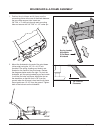
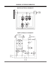
MOLDBOARD & A-FRAME ASSEMBLY
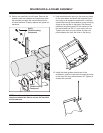
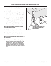
5. Remove the plastic dust caps from the hydraulic
lift cylinder ports. Attach one 9/16"-18 x 9/16"-18
45° adjustable elbow O.R.B. adapter (B60272) to
the driver’s side port (base end) and one
9/16"-18 x 9/16"-18 male O.R.B. connector
adapter (B60007) to the passenger’s side port
(rod end). Once the adapters have been installed
on the cylinder, connect the hydraulic hoses.
Tighten fittings and hoses per torque chart.
NOTE: Position the 45° fitting in the cylinder port
so that the hoses install directly in the center of
the A-frame access holes. A hose installed too
close to the edge of the opening may work itself
free with the operation of the lift cylinder and/or
movement of the plow.
The 45° adapter receives a 3/8" x 17" hydraulic
hose (B60273). Connect the 45° angle on the
hose to the hydraulic adapter on the cylinder. The
male connector adapter receives a 3/8" x 15"
hydraulic hose (B60274). Connect the 45° end of
the hose to the hydraulic adapter on the cylinder.
Both hoses should be routed through the
triangular openings in the A-frame. Tighten fittings
and hoses per torque chart.
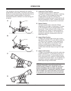
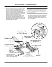
3. Position each angle cylinder with the rod end of
the cylinder in the pivot beam and the hydraulic
hose port facing away from the A-frame. Secure
the cylinder to the pivot beam with a 3/4" x 5"
clevis pin (B41051) and a 1/4" x 1-1/2" cotter pin
(B61357). Extend each cylinder rod until the
cylinder base mounting hole aligns with the hole
on the A-frame angle cylinder bracket. Insert
another clevis pin and secure it with a cotter pin.
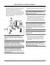
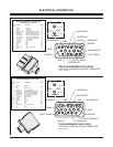
4. Remove the dust cap from both of the hydraulic
angle cylinder ports and attach one
9/16"-18 x 9/16"-18 90° adjustable elbow O.R.B.
adapter (B60005) to each port. Each adapter
should be angled toward the top of the moldboard.
Connect one 3/8" x 24" hydraulic hose (B60091)
to each angle cylinder adapter. Be careful not to
over tighten the hose connections. Route both
hoses over the TOP of each cylinder. This will
prevent them from hanging or being pinched.
Tighten fittings and hoses per torque chart.