


Lit. No. B64090, Rev. 00 11 April 1, 2006
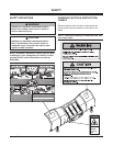
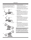
MOLDBOARD & A-FRAME ASSEMBLY
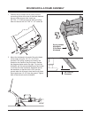
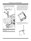
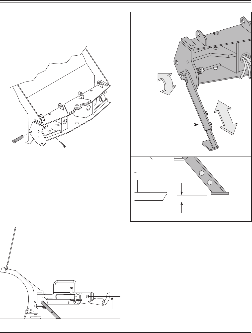
12-1/2"
1/8" Ground
Clearance
Spring Loaded
Adjustable
Pivot Beam
Kickstand
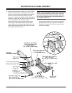
1. Position the pivot beam and A-frame near the
connecting points at the rear of the blade between
the two center support ribs. Insert one
3/4" DIA. x 3" clevis pin through each mounting
hole and secure with 1/4" DIA. x 1-1/2" cotter pin.
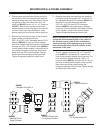
2. Mount the kickstand to the end of the pivot beam
(driver side) using the 1/2"-13 x 4-1/2" bolt
provided. The spring, bushing and locknut are
located on the inside of the pivot beam. Review
the diagrams below and to the right. To pivot the
kickstand, pull the spring loaded leg out and rotate
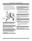
it until the pin locks into place. Adjust the foot on
the stand arm so that the foot is 1/8" from the
ground when the A-frame is level and the A-frame
mount points are 12-1/2" from the ground. Tighten
both of the locknuts on the kickstand.