April 1, 2006 14 Lit. No. B64090, Rev. 00
MOLDBOARD & A-FRAME ASSEMBLY
7. Assemble the manifold. The manifold, pump and
coil harness have been connected at the factory;
however, the manifold contains several
components that you will need to install prior to
securing the assembly to the A-frame. Each of the
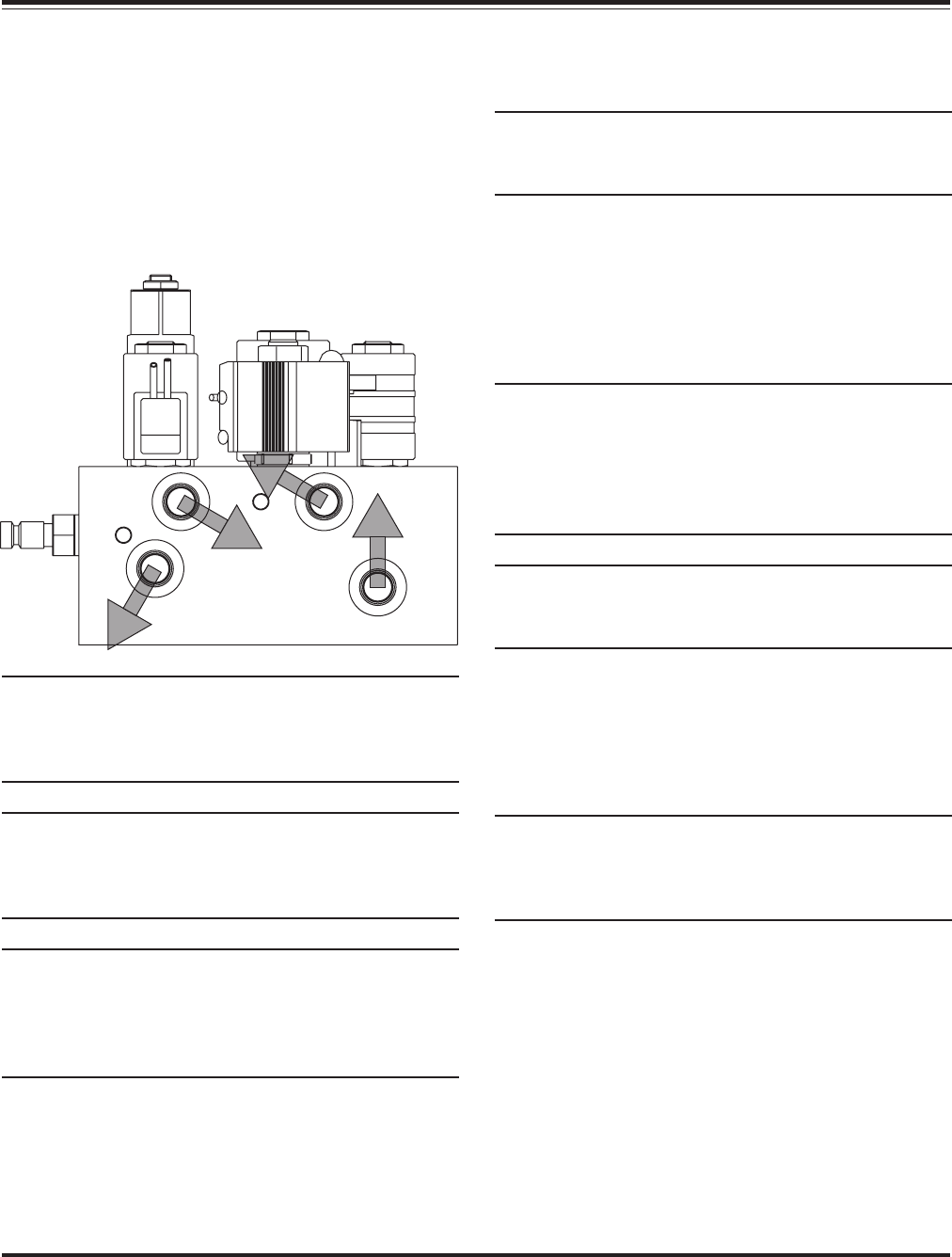
hose ports on the manifold is covered with stretch
wrap. Remove the wrap and install the appropriate
fitting in its respective port. Tighten fittings and
hoses per torque chart.
NOTE: The arrows shown on the manifold
illustration indicate the direction the 90° adapters
should be positioned to receive the hydraulic
hoses.
NOTE: DO NOT let any foreign objects enter into
the open ports. The valves can become
contaminated and greatly hinder the plow’s
performance. Torque to proper specifications.
NOTE: All ports are identified by a stamped
number on the manifold. The numbers also
identify the hydraulic functions, which can be
referenced on the label under the hydraulic pump
and manifold cover.
8. Align the mount holes in the pump with the holes
in the hinged bracket, located on the A-frame.
NOTE: Before mounting the pump, angle the
hinged bracket as needed and tighten the bracket
hardware to lock it in place.
Secure with 3/8"-16 x 3/4" hex head cap screw and
3/8" flat washer through the top mount hole in the
bracket and into the pump. Insert 3/8"-16 x 1-3/4"
threaded stud with 3/8"-16 locknut through the
bottom mount hole in the bracket and into the pump.
The threaded stud should bottom out in the pump.
NOTE: When installing the manifold between the
mount brackets on the A-frame, hold the manifold
at the sides of the block. Never handle the
manifold by coils. Doing so can cause a solenoid
cartridge to bend, causing the cartridge to stick
when activated.
NOTE: A medium strength thread-locking
compound should be used on both of the pump
mount fasteners.
9. Connect the hydraulic hoses to their respective
adapters on the manifold. Hose P/N B60091
Ports #1 & #2, Hose P/N B60273 Port #3 and
Hose P/N B60274 Port #4. Tighten hoses per
torque chart.
NOTE: Both lift cylinder hoses should be routed
through the triangular openings in the A-frame.
Position these hoses over the A-frame angle and to
their respective manifold ports.
32
1
4


