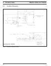
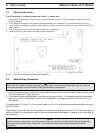
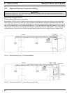
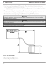
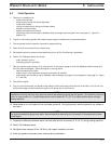
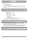
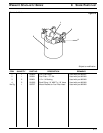
5.8.4 Timer and Switch Installation
1. Locate appropriate switch knock-out (blank) on instrument panel for heater On/Off switch or select a suitable
location in the vehicle dash for the (optional) timer.
2. Remove switch knock-out and replace with appropriate switch. Timer is supplied with a removable
stick-on drilling template.
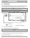
3. Route and secure switch harness from the heater to the vehicle dashboard. If possible use existing hole in fire
wall/ panel or drill in suitable location. Protect the harness with a grommet whenever passing through fire
wall/ panel holes.
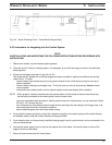
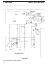
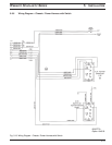
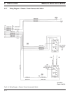
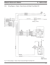
4. Connect the terminals to the switch or timer. See pages 5-13, 5-14, 5-15 and 5-16 for complete wiring details.
CAUTION
Make sure there is enough space behind the dash for the switch or timer and wire connections before cutting any
holes.
CAUTION
To prevent damage to electrical and mechanical components, check for clearance before drilling into panels and
frame members.
W
EBASTO
S
CHOLASTIC
S
ERIES
5INSTALLATION
5-11
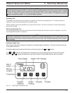
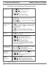
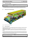
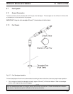
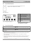
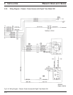
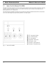
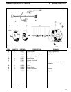
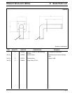
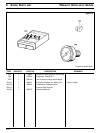
5.8.3 Timer and Switch Connections
Fig. 5-10: On/Off Switch
Fig. 5-11: 7-Day Digital Timer Model 1531
For switch connection details (pin-outs) see wiring diagrams (fig.5-13, 5-14)
on pages 5-13 and 5-14 appropriate to your installation.
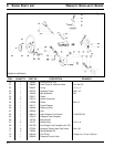
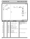
1 Vehicle Dash Lights (Optional)
2 Terminal 86 of Relay K1
4 Chassis Ground (Negative)
8 To Control Unit Terminal Location B3
10 To Vehicle Ignition Signal (Positive)
11 Terminal 87 of Relay K1 or Constant
12 Chassis Ground (Negative)
3, 5, 6, Not Used
7 and 9
Pin-Out
Connect To:
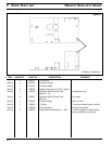
For timer connection details (pin-outs) see
wiring diagrams (fig.5-15, 5-16) on pages 5-15
and 5-16 appropriate to your installation.