W
EBASTO
S
CHOLASTIC
S
ERIES
5INSTALLATION
5-3
WARNING
Due to the risk of carbon monoxide poisoning and asphyxiation, never draw combustion air from inside the vehicles
passenger compartment.
5.5 Combustion Air Supply
1. Never draw combustion air from inside the vehicle, or from areas where fumes or gases can accumulate.
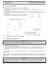
2. The installation housing must provide adequate ventilation for combustion air requirements [20 cm² (4 in²)].
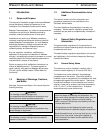
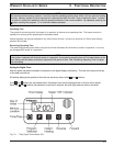
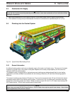
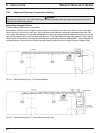
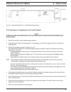
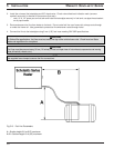
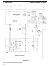
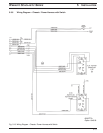
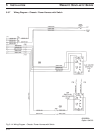
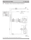
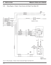
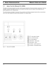
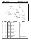
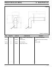
Fig. 5-3: Typical School Bus Heating Circuit
5.6.1 General Information
An efficient heating system must have an adequate supply of hot water to all heater cores. The amount of hot water
available to a typical three or four heater-core system depends on the water pumps capability and the amount of
restriction within the coolant system.
The Webasto heater is equipped with a high-performance circulating pump designed specifically for bus heating
applications, and when plumbed in accordance with the following instructions, will maximize the heating systems
efficiency.
The coolant-circulating pump (bottom of Enclosure or Tray) must be mounted at least 150 mm (6”) below the lowest
permissible coolant level of the vehicles cooling system. A minimum of 10% of a good quality antifreeze should be
maintained in the cooling system at all times. Heater and water pump fit 25.4 mm (1”) ID. heater hose meeting SAE
20 R3 specifications. Silicone hose requires special hose clamps.
NOTE:
Heater hose must meet SAE 20 R3 specifications. Silicone heater hose requires special hose clamps. Hose clamps
must be tightened to 5 Nm (45 lb/in.) torque.
5.6 Plumbing into the Coolant System