5INSTALLATION
W
EBASTO
S
CHOLASTIC
S
ERIES
5-2
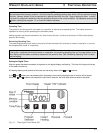
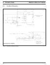
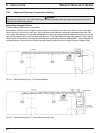
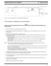
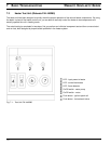
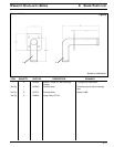
5.3 Mounting the Heater
Tray Kit mounting in existing enclosure on vehicle, i.e. battery box.
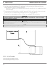
1. Ensure that the enclosure is large enough to accommodate the heater. Use the installation template provided
with the heater kit.
2. The installation enclosure must provide adequate ventilation for combustion air requirements [20 cm² (4 in²)].
3. Lay the supplied installation template in the enclosure. Center punch the exhaust, fuel, electrical and 4 mounting
hole locations.
4. Drill all required holes to the dimensions as shown on the template.
5. Solidly bolt the tray with heater mounted inside the enclosure.
Fig. 5-2: Tray Mount Template (Supplied with Heater Kit)
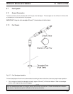
5.4 Exhaust Pipe Connection
WARNING
Due to the risk of carbon monoxide poisoning and asphyxiation, exhaust system components must be routed in a
manner that prevents exhaust fumes from entering the passenger compartment.
1. Insert the supplied flexible exhaust pipe to the heater and fasten with the exhaust clamp. Fasten the outlet end to
the chassis with the “P” clamp provided.
2. The exhaust system must discharge on the street (driver) side of vehicle. The discharge opening of the exhaust
pipe must not point in the direction of travel, and so located that any clogging caused by snow or mud is not to
be expected.
The exhaust pipe I.D. 38 mm (1 1/2”) can have a length up to 5 m (16’) and may have several bends totaling no more
than 270° overall.
Rigid exhaust pipe may be used; bends must be formed (smallest bending radius 85 mm (3 3/8”). Do not weld pipe to
make 90° corners. Any condensation water in the exhaust pipe must be discharged. If necessary, drill a drain hole at
the lowest point.
NOTE:
Route the exhaust components in a way that prevents them from touching vehicle parts that may be damaged by
heat (brake lines, electrical wiring, hoses, etc.). Do not direct exhaust outlet towards heat sensitive vehicle
components.