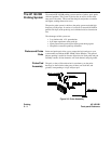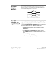
Connecting the
Probes
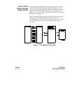
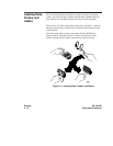
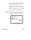
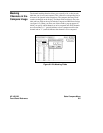
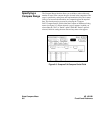
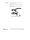
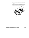
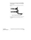
At this point, if you had a target system with a 68000 microprocessor, you
would connect the logic analyzer to your system. Since you have assigned
labels ADDR and DATA, you would hook the probes to your system
accordingly.
• Pod1probes0through15tothedatabuslinesD0throughD15.
• Pod2probes0through15totheaddressbuslinesA0throughA15.
• Pod 3 probes 0 through 7 to the address bus lines A16 through A23.
• Pod 1, CLK (J clock) to the address strobe (LAS).
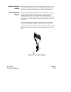
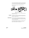
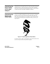
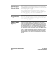
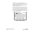
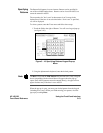
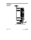
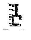
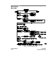
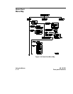
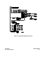
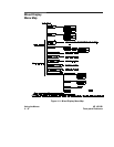
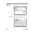
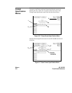
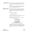
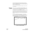
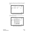
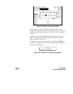
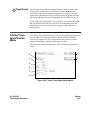
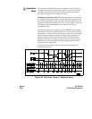
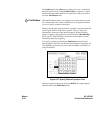
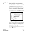
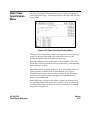
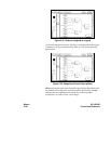
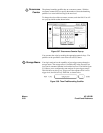
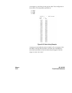
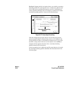
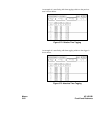
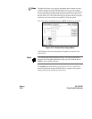
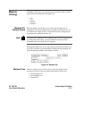
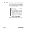
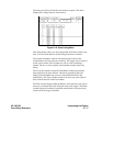
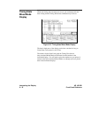
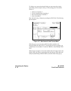
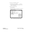
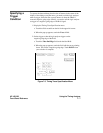
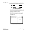
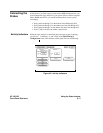
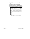
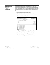
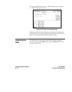
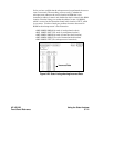
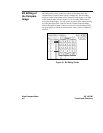
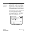
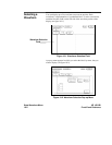
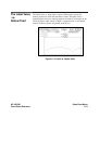
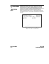
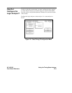
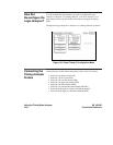
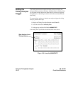
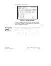
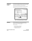
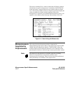
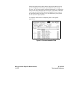
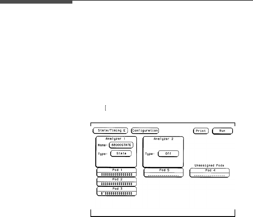
Activity Indicators When the logic analyzer is connected and your target system is running,
youwillsee inthePod1,2,and3fieldsoftheState/Timing E
Configuration menu. This indicates which signal lines are transitioning.
Figure 8-2. Activity Indicators
HP 16510B Using the State Analyzer
Front-Panel Reference 8 - 5