


8
In Y-axis single slope mode, the Y-axis can be sloped by pressing the Up- and Down-Arrow-buttons on the
laser or the remote control, while the X-axis remains in automatic self leveling mode (e.g. when setting up
sloped ceilings or drive ways).
To activate the X-axis single slope mode, press the manual button (1 second) after the right arrow button at
the remote control has been pressed and released. This is indicated by the simultaneously fl ashing red 5 and
green 4 LEDs (every 3 seconds).
In X-axis single slope mode, the X-axis can be sloped by pressing the right- and left-Arrow-buttons on the
remote control, while the Y-axis remains in automatic self leveling mode
To resume automatic self-leveling mode, press the manual button again.
APPLICATIONS
Interior
Acoustical Ceilings
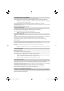
1. Determine and mark the fi nished ceiling height and securely install
the fi rst piece of wall molding to this height.
2. Attach the laser onto the wall molding by sliding the wall mount
clamp over the wall molding and pulling down the locking lever.
3. To adjust the elevation, release the elevation clamp, slide the laser
to the zero (0) mark on the scale (wall molding elevation), and lock
the elevation clamp.
Note: To minimize accidental dropping, insert a ceiling wire
through one of the holes and twist the wire.
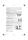
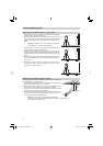
Drywall and Partitions
1. Attach the laser to the sliding bracket.
2. Place the laser over the near wall-control point.
3. Use the up/down arrow button to point the beam towards the far wall-control
point.
4. Go to the far wall-control point and use the remote control to adjust the line
of the laser until the laser beam is aligned to the mark.
5. Install the track or mark the track line on both the fl oor and ceiling for future
track installation.
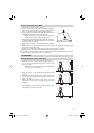
Transferring Plumb Points to the Ceiling
The origin of the laser beam is located directly above the horizontal tripod mount and the height of the vertical
tripod mount.
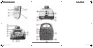
In order to transfer a marked point from the bottom to the ceiling, there are cross center marks 12 at the lower
part of the unit‘s bottom housing. Using these marks, the unit may be set up with the two axes X and Y above
two crossed chalk marks, for example.
For better installation of the unit above a mark on the fl oor, just mark 2 rectangular lines through this point.
General Construction
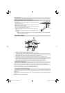
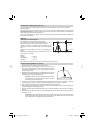
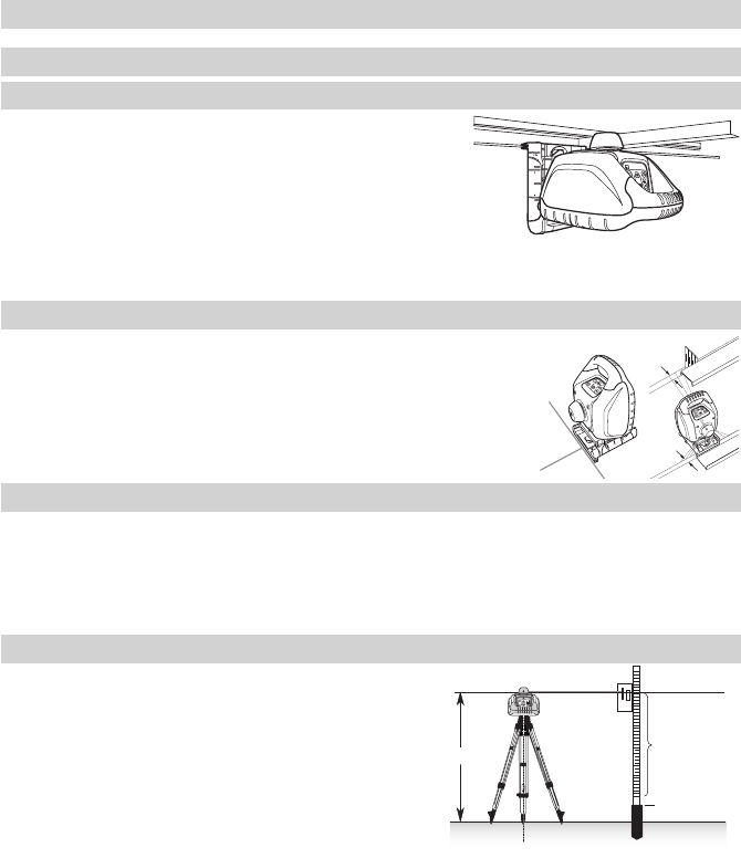
Determining the Height of Instrument (HI)
The height of instrument (HI) is the elevation of the laser’s
beam.
The HI is determined by adding the grade-rod reading to a
benchmark or known elevation.
1. Set up the laser and place the grade rod on a job-site
benchmark (BM) or known elevation.
2. Slide the receiver up/down the grade rod until it shows an
on-grade reading.
3. Add the grade-rod reading to the benchmark to determine the
height of instrument.
Example:
Benchmark = 30.55 m (100.23 ft)
Rod reading = +1.32 m (+4.34 ft)
Height of instrument = 31.87 m (104.57 ft)
Use this HI as a reference for all other elevations.
5 cm (2 in.)
5 cm (2 in.)
1.32 m (4.34 ft)
30.55 m (100.23 ft)
HI
071016_01_HV101_GB.indd 8071016_01_HV101_GB.indd 8 27.11.2007 15:13:19 Uhr27.11.2007 15:13:19 Uhr