


GM862-GPS Hardware User Guide
1vv0300728 Rev. 0 - 27/04/06
Reproduction forbidden without Telit Communications S.p.A. written authorization - All Right reserved page 46 of 55
7.3 Using the Alarm Output GPIO6
The GPIO6 pin, when configured as Alarm Output, is controlled by the GM862-GPS module and will
rise when the alarm starts and fall after the issue of a dedicated AT command.
This output can be used to power up the GM862-GPS controlling microcontroller or application at the
alarm time, giving you the possibility to program a timely system wake-up to achieve some periodic
actions and completely turn off either the application and the GM862-GPS during sleep periods,
drammatically reducing the sleep comsumption to few μA.
In battery powered devices this feature will greatly improve the autonomy of the device.
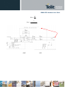
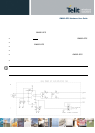
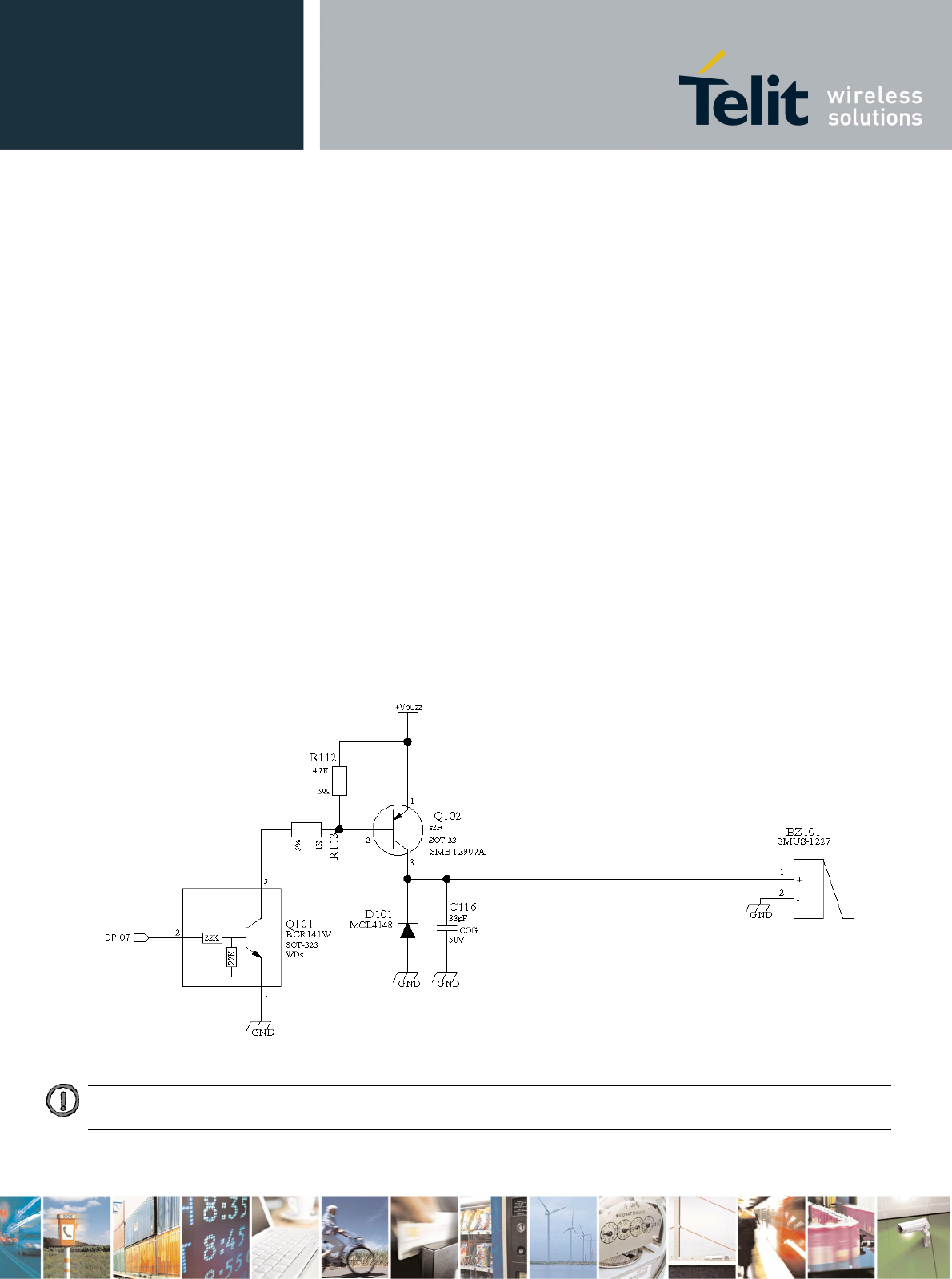
7.4 Using the Buzzer Output GPIO7
The GPIO7 pin, when configured as Buzzer Output, is controlled by the GM862-GPS module a nd will
drive with appropriate square waves a Buzzer driver.
This permits to your application to easily implement Buzzer feature with ringing tones or melody
played at the call incoming, tone playing on SMS incoming or simply playing a tone or melody when
needed by your application.
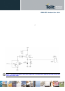
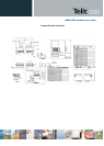
A sample interface scheme is included below to give you an idea of how to interface a Buzzer to the
GPIO7:
NOTE: To correctly drive a buzzer a driver must be provided, its characteristics depend on the Buzzer and for them
refer to your buzzer vendor.