


GM862-GPS Hardware User Guide
1vv0300728 Rev. 0 - 27/04/06
Reproduction forbidden without Telit Communications S.p.A. written authorization - All Right reserved page 34 of 55
5.5 Microphone buffering
As seen previously, a microphone shall be connected to the input pins of the GM862-GPS through a
buffer amplifier that boosts the signal level to the required value.
Again the buffered microphone circuitry can be balanced or unbalanced: where possible it is always
preferable a balanced solution. The buffering circuit shall be placed close to the microphone or close
to the microphone wire connector.
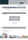
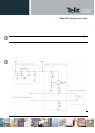
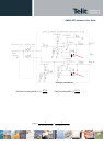
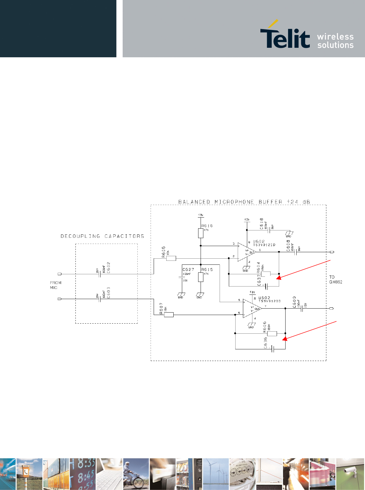
5.5.1 Buffered Balanced Mic.
A sample circuit can be:
This circuit has a gain of 10 times (+20 dB), and is therefore suited for the “Mic_MT “ input if you have
a microphone with a sensitivity close to the suggested one (-45 dBV
rms/
Pa). If your microphone has a
different sensitivity or if the buffer is connected to the “Mic_HF “ inputs , then a gain adjustment shall
be done by changing resistors R604 and R606 ( if the required value is not a standard one , you can
change R605 e R607 ) and as a consequence the capacitors C636 and C637 to maintain the
bandwidth 150-4000Hz (at -3dB).
270pF
270pF