


GM862-GPS Hardware User Guide
1vv0300728 Rev. 0 - 27/04/06
Reproduction forbidden without Telit Communications S.p.A. written authorization - All Right reserved page 41 of 55
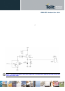
6.3 General Design rules
There are several configurations for the audio output path, but the various design requirements can be
grouped into three different categories:
• handset earphone (low power, typically a handset)
• hands-free earphone (low power, typically a earphone)
• car kit speakerphone (high power, typically a speaker)
The three groups have different power requirements, usually the first two applications need only few
mW of power, which can be directly drained from the GM862-GPS pads, provided a suited speaker is
used. This direct connect design is the cheaper and simpler solution and will be suited for the most of
the earphone design requirements. There's no need to decouple the output ear lines if a suited
earpiece is connected. For the last group, the speakerphone, a power amplifier is required to raise the
output power up to 5-10W required in a car cabin application.
All the designs shall comply with the following guidelines:
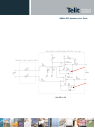
• Where possible use a bridged earphone circuitry, to achieve the maximum power output from the
device.
• Keep the earphone traces on the PCB and wires as short as possible.
• If your application requires a single ended earpiece and you want a direct connection, then leave
one of the two output lines open and use only the other referred to ground. Reme mber that in this
case the power output is 4 times lower than the bridged circuit and may not be enough to ensure
a good voice volume.
• Make sure that the earphone traces in the PCB don't cross or run parallel to noisy traces
(especially the power line)
• The cable to the speaker shall be a twisted pair with both the lines floating for the bridged output
type, shielded with the shield to ground for the single ended output type.
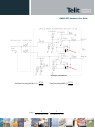
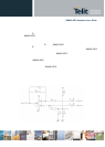
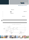
6.3.1 Noise Filtering
The I/O of the PCB should have a noise filter close to the connector, to filter the high frequency GSM
noise. The filter can be a Π formed by 2 capacitor and a inductance, with the one capacitor of 39pF -
0603 case , and the other capacitor of 1nF - 0603; the inductance shall have a value of 39μH .