


141-072011 - 201/203 Series Page 9 of 23
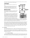
2.4. Mechanical Connections
The flow meter may be mounted in any position as long as the direction of gas flow through the
instrument follows the arrow marked on the bottom of the flow meter case label. The preferred
orientation is with the inlet and outlet fittings in a horizontal plane (if operating with a dense gas or at
high pressures the instrument must be installed horizontally). When mounted in a different
orientation the instrument should be re-zeroed at zero flow with the system pressurized to the
expected operating pressure.
The smallest of the internal passageways in the Hastings 200 series flow instrument is the diameter
of the sensor tube, which is 0.0125”(0.31 mm), so the instrument requires adequate filtering of the
gas supply to prevent blockage or clogging of the tube.
The pressure regulator and the plumbing upstream must be of sufficient size to minimize changes in
the upstream pressure. When switching from full flow to zero flow, the inlet pressure of the
instrument should rise to no more that 30% above the inlet pressure at full flow. In general, high
capacity regulators and large internal diameter plumbing help to make the system more stable. The
pressure drop between the regulator and the instrument due to line resistance should be minimized.
The differential pressure across the unit should be less than 6” of H
2
O at maximum flow.
There are two 8-32 threaded holes, 0.25” deep, (1/4-28 threaded holes, 0.375” deep for 205/207)
located on the bottom of the base that can be used to secure it to a mounting bracket, if desired
(screws provided). Other holes for special mounting can be added to the end cap as desired.
The standard inlet and outlet fittings for the 201/203 are 0.5” and 0.75” Swagelok (optional VCR,
VCO, NPT and metric fittings are available). The standard inlet and outlet fittings for the 205/207
are 1” Swagelok (optional VCR, VCO, and metric fittings are available).The O-rings for the end cap
and the sensor are Viton (optional Kalrez , Buna-N (Nitrile) or Neoprene is available). It is
suggested that all connections be checked for leaks after installation. This can be done by
pressurizing the instrument (do not exceed 500 psig unless the flow meter is specifically rated for
higher pressures) and applying a diluted soap solution to
the tubing connections.
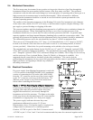
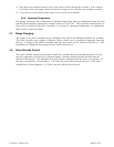
2.5. Electrical Connections
If a power supply from Hastings Instruments is used with
a 15 Volt version of the HFM-200/HFC-202, installation
consists of connecting the 200 series cable (#AF-8AM)
from the “D” connector on the rear of the power supply
to the “D” connector on the top of the flow meter. If a
different power supply is used, follow the instructions
below when connecting the flow meter.
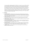
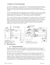
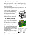
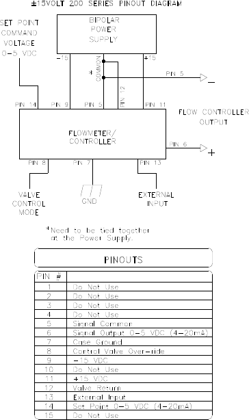
Bipolar (±15 Volt) Power Supply to Bipolar Connections
Connecting the Hastings 200 series flow instrument with
anything other than the prescribed cables and power
supplies discussed above, can severely damage the
instrument and void the warranty. The figure at the right
of this page shows the schematic layout for connecting the
instrument to an appropriate ±15 Volt power supply.
The power supply used must be meet the power
requirements delineated in section 2.2 (Power
Requirements) above. If a bipolar supply is required, the
voltages must be referenced to a common ground.
Connect -15VDC to pin 9 of the DA-15 connector and
+15VDC to pin 11. Pins 5 and 12 are both commons and they must be connected together and to