


141-072011 - 201/203 Series Page 11 of 23
some zero offset.) The 201/203 series is intended for use in non-condensing environments only.
Condensate or any other liquids which enter the flow meter may destroy its electronic components.
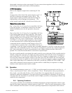
2.6.2. Zero Check
Turn the power supply on if not already energized. Allow for a 1 hour warm-up. Stop all flow
through the instrument and wait 2 minutes. Caution: Do not assume that all metering valves
completely shut off the flow. Even a slight leakage will cause an indication on the meter and an
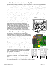
apparent zero shift. For the standard 0 - 5 VDC output, adjust the zero potentiometer located on
the lower outlet side of the flow meter until the meter indicates zero. For the optional 4 - 20 mA
output, adjust the zero potentiometer so that the meter indicates slightly more than 4 mA, i.e. 4.03 to
4.05 mA. This slight positive adjustment ensures that the 4 - 20 mA current loop transmitter is not
in the cut-off region. The error induced by this adjustment is approximately 0.3% of full scale. This
zero should be checked periodically during normal operation. Zero adjustment is required if there is
a change in ambient temperature, or vertical orientation of the flow meter/controller.
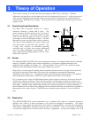
2.6.3. High Pressure/High Density Operation
When operating at high pressure or with high density gases, the increased density of gas will cause
natural convection to flow through the sensor tube if the instrument is not mounted in a level
position. This natural convection flow will be proportional to the system pressure. This will be seen
as a shift in the zero flow output that is directly proportional to the system pressure. This zero shift
can usually be corrected by adjusting the zero potentiometer after mounting the flow controller in its
final operating position. See section 2.4 and 2.6.2.
Additionally, because the specific heat of a gas changes with pressure, an associated error is
introduced with increased pressure. It is directly proportional to the change in specific heat versus
pressure for that particular gas. For helium, there is virtually no change in indicated output; for
nitrogen, the indicated output will increase at approximately 0.0067%/psi, which is the pressure
coefficient. Thus,
Actual flow = indicated flow / (1 + pressure * pressure coefficient)
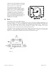
2.6.4. Blending of Gases
In the blending of two gases, it is possible to maintain a fixed ratio of one gas to another. In this
case, the output of one flow controller is used as the reference voltage for the set point potentiometer
of a second flow controller. The set point potentiometer then provides a control signal that is
proportional to the output signal of the first flow controller, and hence controls the flow rate of the
second gas as a percentage of the flow rate of the first gas.
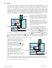
EXAMPLE: Flow controller A has 0 - 100 slm range with a 5.00 Volt output at full scale. Flow
controller B has 0 - 10 slm range with a 5.00 Volt output at full scale. If flow controller A is set at 80
slm, its output voltage would be 4.00 Volts (80 slm/100 slm x 5.00 Volts = 4.00 Volts). If the output
signal from flow controller A is connected to the command potentiometer of flow controller B, it
then becomes a variable reference voltage for flow controller B proportional to the flow rate of flow
controller A.
If the set point potentiometer of flow controller B is set at 50% of full scale, and the reference voltage
from flow controller A is 4.00, then the command signal going to flow controller B would be 2.00
Volts (4.00 Volts x 50.0% = 2.00 Volts). The flow of gas through flow controller B is then
controlled at 4 slm (2.00 Volts/5.00 Volts x 10 slm = 4 slm).
The ratio of the two gases is 20:1 (80 slm/4slm). The % mixture of gas A is 95.2 (80slm/84slm and
the % mixture of gas B is 4.8% (4 slm/84 slm).
Should the flow of flow controller A drop to 78 slm, flow controller B would drop to 3.9 slm, hence
maintaining the same ratio of the mixture. (78 slm/100 slm x 5 Volts = 3.90 Volts x 50% = 1.95
Volts; 1.95 Volts /5.00 Volts x 10 slm = 3.9 slm; 78 slm: 3.9 slm = 20:1)