


141-072011 - 201/203 Series Page 13 of 23
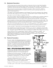
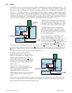
2.6.7. Operation with an external sensor. (Fig. 2.2)
In some instances, it might be desirable to use an external sensor to provide process information to
the control circuitry in the flow controller. For example, you might want to control the pressure in a
vacuum system by adjusting the rate at which the system is backfilled with a gas. The new,
enhanced HFC series of flow controllers have provision for accepting a 0 - 5VDC (or 0 - 10 VDC)
output from an external sensor at pin 13 of the DA-15 (±15 Volt), Pin 1 of the DE-9 (24 Volt)
connector. To activate this feature, the cover of the HFC must be removed to gain access to the
electronics card and move a jumper.
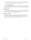
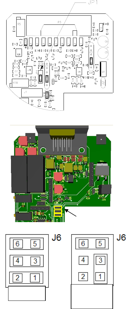
For the 15 Volts units JP1 is a three pin jumper block located just below the “D” connector. In the
normal operating mode, the jumper covers the bottom two pins. To select “External Sensor”, move
the jumper to the upper two pins. This swaps the flow input to the controller circuit from the flow
meter output to pin 13 of the “DA-15” connector.
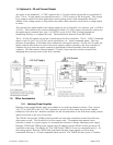
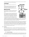
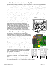
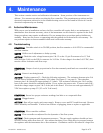
For the 24 Volt units JP6 is a six pin jumper block located
just to the right of the sensor connector. Pin 1 is in the
lower right corner. There are three jumpers installed
horizontally. The bottom jumper ties the flow output to
the valve control circuit and the middle jumper ties Pin 1
of the DE-9 connector to reference voltage circuit.
Remove both of the lower two jumpers and reinstall one
jumper vertically between the outside two pins (pins 1 &
3). This will tie Pin 1 of the DE-9 connector to the valve
control circuit and allow the controller to maintain the
external process variable equal to the desired setpoint.
The 5 Volt reference is not available in this configuration.
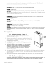
2.6.8. Response to Command Changes
The response of the control circuit to changes to the
command signal is set at the factory for fast, stable response.
If excessive overshoot is present, the response can be slowed
removing the jumper labeled “JP4,” located in the center of
PC-828 for the 15 Volt units or by removing the top jumper
of JP6 for the 24 Volt boards (located to the right of the
sensor connector.
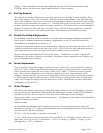
The fastest response to command changes is obtained when
JP4/(JP6) is covered by the jumper. This setup allows large
overshoot and undershoot swings in the actual flow rate while
the control circuit is establishing control at the new command
point. A slower response to command changes is obtained
when JP4/JP6 is not covered by a jumper. This setup results
in no overshoot or undershoot in the actual flow rate as the
controller circuit establishes control at the new command
point. This jumper does not affect the system gain and
will not dampen out oscillations.
To adjust the response, you need a means of producing a
step change in the command voltage from 10% of full
scale to 100% of full scale. Follow the steps outlined
below:
1) Cover the pins of JP4/JP6 with a jumper. (see fig. 2.2 & fig 2.3)
2) Set the command voltage to 10% of full scale. Allow the flow to stabilize.
Fi
g
2.2
JP6
Fig 2.3
Normal
External
Variable