


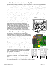

141-072011 - 201/203 Series Page 12 of 23
2.6.5. Operation with a Hastings power supply.
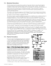
There are two controls for each flow controller connected to a Hastings power supply. A switch
labeled “OPEN; AUTO; CLOSED” (valve override THPS 400 only) and a potentiometer labeled
“COMMAND”. For normal operation, the valve override switch will be in the “AUTO” position.
The “CLOSE” position removes all power from the valve, shutting off flow regardless of the
command pot setting. The “OPEN” position applies full available valve voltage to the valve, causing
it to open, regardless of the command pot setting. The “OPEN” position is useful for purging
systems. It is recommended that the valve override switch not be left in this position for extended
periods of time, with no flow through the controller, as a small positive zero shift may be observed.
The “COMMAND” pot adjusts the Analog command signal sent to the flow controller. The setting
for each controller connected to the power supply can be observed. (Depending on how the power
supply was set up, the display could indicate in flow units or percent of full scale).
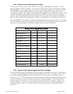
Hastings Power Supply Feature Guide
Feature Model 40
Power Pod 100
Power Pod 400
Digital Readout
9 9 9
±15 Volts
9 9 9
Analog Outputs
9 9 9
Controller
9 9
Analog Control
9
Front Panel Override
9
9
Totalizer
9
4 -20 mA
9
9
Ratio Control
9
Alarms
9 9 9
Multi-Channel Display
9
Conversion Factors
9 9 9
Communications RS232 RS232/RS485
2.6.6. Operation with a power supply other than a Hastings.
The flow controller must be connected to the power source as specified in section 2.6. In general, a
0 - 5 VDC command signal proportional to the intended flow (0 Volts = zero flow; 5 Volts = 100%
of rated flow) must be applied to pin 14 of the DA-15 (±15 Volt), Pin 3 of the DE-9 (24 Volt)
connector. A 0 - 5 VDC signal proportional to the flow rate through the instrument will be present
on pin 6 of the DA-15 (±15 Volt), Pin 2 of the DE-9 (24 Volt) connector. The control mode is
selected via pin 8 of the DA-15 (±15 Volt), Pin 6 of the DE-9 (24 Volt) connector. Apply >10
Volts for full open, < 0 Volts for closed and allow the override to float for flow proportional to the
command voltage. Refer to your power supply manual for the specifics of implementing these
parameters.