


141-072011 - 201/203 Series Page 19 of 23
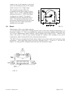
restriction is pneumatically close to the downstream end of the flow controller. The differential
pressure across the unit must be between 10-50 psig.
SYMPTOM: Little or no flow, even with Valve Override switch OPEN.
CAUSE: Plugged orifice.
ACTION: Verify the presence of a 10-50 psig pressure across the instrument. If present, shut off
gas supply and power supply. Remove orifice per Section 4.9. Examine orifice. If plugged, clean or
replace as applicable. Reassemble valve.
SYMPTOM: Flow meter reads other than 0.00 VDC with no flow, or there is a small flow when
flow meter reads 0.00 VDC.
CAUSE: ZERO potentiometer is out of adjustment.
ACTION: Shut off all flow. Adjust ZERO potentiometer until output reads 0.00 VDC.
SYMPTOM: Flow meter out of calibration and nonlinear.
CAUSE: Leaks in gas inlet or outlet fittings.
ACTION: Check all fittings for leaks by placing soap solution on all fittings between gas supply and
final destination of gas. Check flow meter for leaks. Replace “O” rings if required or recalibrate as
necessary.
4.3. Adjustments
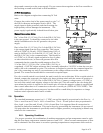
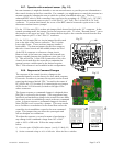
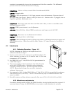
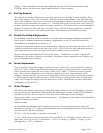
4.3.1. Calibration Procedure: (Figure 4.1)
NOTE: Adjusting the SPAN pot will require the use of a
calibration reference in Step 5.
1) Connect power cable to D connector as specified in Section 2.7.
Allow instrument to warm up for 30 minutes with 10% flow and
instrument in AUTO position.
2) Set ZERO (R13 on 15 Volt, R20 for 24 Volt) potentiometer for
0.000 VDC output.
3) Turn on gas supply to inlet of instrument. Put Valve Override
switch into CLOSE position. Adjust the orifice underneath
controller to obtain zero flow. Put Valve Override switch into
AUTO. Ensure that full range flow can still be obtained at
minimum inlet pressure.
4) Set command to 100%. Adjust SPAN (R18 on 15 Volt, R2 for 24 Volt) pot until the flow reference
reads full scale flow (5.000 VDC). NOTE: Perform this step only if a calibrated reference flow
meter is available.
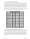
5) Record flow meter and flow reference outputs for flow rates of 20%, 40%, 60%, 80% and 100%.
4.3.2. Miscellaneous adjustments
Periodically, during normal operation, the ZERO should be checked and adjusted when required. If
system parameters change, the RESPONSE pot may require a small adjustment for optimum