


ME(H4DOTC)-41
MECHANICAL
Valve Clearance
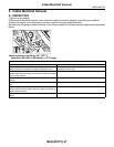
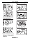
(5) Move the washer tank upward.
(6) Disconnect the ignition coil connector.
(7) Remove the ignition coil.
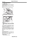
(8) Place a suitable container under the vehicle.
(9) Disconnect the PCV hose from rocker cover
(LH).
(10)Remove the bolts, and then remove the
rocker cover (LH).
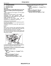
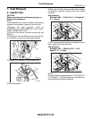
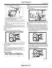
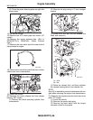
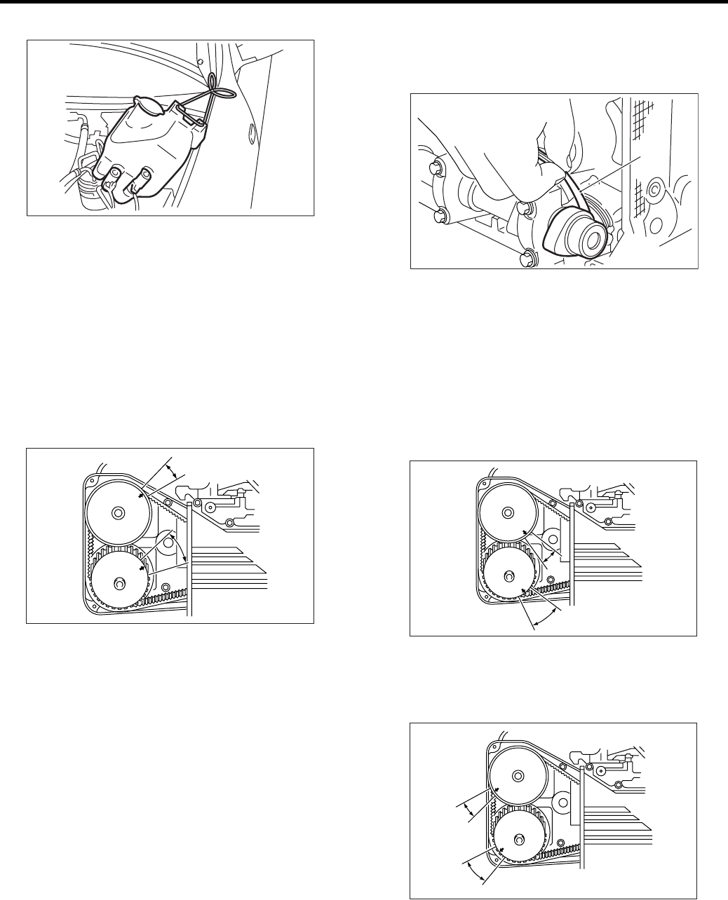
11) Turn the crankshaft pulley clockwise until arrow
mark on the camshaft sprocket is set to position
shown in the figure.
NOTE:
Turn the crankshaft using socket wrench.
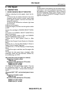
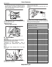
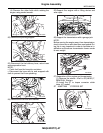
12) Measure the #1 cylinder intake valve and #3
cylinder exhaust valve clearance by using thick-
ness gauge (A).
NOTE:
• Insert the thickness gauge in as horizontal a di-
rection as possible with respect to the shim.
• Measure the exhaust valve clearances while lift-
ing-up the vehicle.
Valve clearance:
Intake: 0.20
±
±±
±
0.02 mm (0.0079
±
±±
±
0.0008 in)
Exhaust: 0.35
±
±±
±
0.02 mm (0.0138
±
±±
±
0.0008 in)
NOTE:
If the measured value is not within specification,
take notes of the value in order to adjust the valve
clearance later on.
13) If necessary, adjust the valve clearance. <Ref.
to ME(H4DOTC)-42, ADJUSTMENT, Valve Clear-
ance.>
14) Further turn the crankshaft pulley clockwise.
Using the same procedures described previously,
and then measure the valve clearances again.
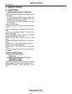
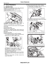
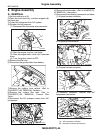
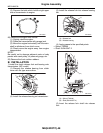
(1) Set the arrow mark on camshaft sprocket to
position shown in the figure, and then measure
the #2 cylinder exhaust valve and #3 cylinder in-
take valve clearances.
(2) Set the arrow mark on camshaft sprocket to
position shown in the figure, and then measure
the #2 cylinder intake valve and #4 cylinder ex-
haust valve clearances.
ME-00017
ME-00733
ME-00019
(A)
ME-00734
ME-00735