


PAGE 42 — LT-12 SERIES LIGHT TOWER — OPERATION MANUAL — REV. #1 (08/15/08)
LT-12 SERIES LIGHT TOWER — TROUBLESHOOTING (LAMPS)
TROUBLESHOOTING GUIDE
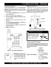
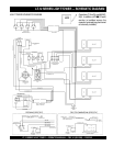
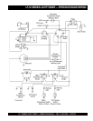
Use the following procedure and wiring diagram on the opposite page to determine which of the four floodlights is not functioning:
Connections:
1. Make sure that floodlight #1 power cable is plugged into the J1 connector on the T-Bar assembly.
2. Make sure that floodlight #2 power cable is plugged into the J2 connector on the T-Bar assembly.
3. Make sure that floodlight #3 power cable is plugged into the J3 connector on the T-Bar assembly.
4. Make sure that floodlight #4 power cable is plugged into the J4 connector on the T-Bar assembly.
5. With the voltmeter set to the AC position, connect the negative lead of the AC voltmeter to any (neutral) white wire on
the junction terminal block. This blocks connects all the neutral wires (white) in the system.
6. Connect the positive lead of the voltmeter to the output side of CB1, and observe that 120 VAC is present. Make sure
circuit breaker is ON.
7. Repeat step 1-6 for CB2 thru CB4.
8. If the correct output voltages are present for CB1 thru CB4 then it can be assumed that the generator is working
correctly and the correct voltage (120 VAC) are being supplied to the ballast.
Starting:
1. Start the generator and verify that there are no abnormal sounds.
2. Turn CB1 thru CB4 circuit breakers to the ON position.
3. Wait a few minutes and determine which flood light is not igniting.
4. If one of the floodlights is OFF, disconnect its power cable and plug it into a receptacle that is known to be working. DO
NOT unplug a power cable from the T-Bar while power is being supplied by the generator. Always turn the circuit breaker
OFF before un-plugging a power cable.
5. If the floodlight still does not ignite after plugging it into a working receptacle (120 VAC present), then it can be assumed
that the ballast for that flood light is defective. Replace ballast.
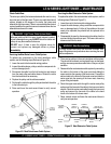
Ballast Removal:
1. Remove the power cable from the generator or welder, and make sure that no voltage is being supplied to the ballast
compartment.
2. Remove the four screws securing the ballast cover, and remove cover.
3. Make sure to discharge the ballast capacitor.
3. Remove the defective ballast, taking care to guard against electrical shock when coming in contact with the ballast and
capacitor. The capacitor is known to store an electrical charge, that when discharged could result in a harmful shock.
Make sure to discharge capacitor.