


LT-12 SERIES LIGHT TOWER — OPERATION MANUAL — REV. #1 (08/15/08) — PAGE 31
LT-12 SERIES LIGHT TOWER — OPERATION
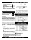
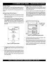
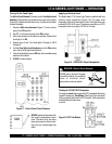
Turning On the Flood Lights
The
Main Circuit Breaker
(25 amps), and 4
floodlight circuit
breakers
(10 amps each) are located on the upper control panel
(Figure 20). Please note that there is one 10 amp circuit breaker
for each floodlight.
1. Place the
Main circuit breaker
(Figure 17) on the control
panel to the ON position.
2. Set CB-1 on the control panel to the ON position.
3. Wait a few minutes for the ballast to activate. Observe that
flood light #1 is ON.
5. Repeat steps 2 and 3 for flood lights 2 through 4 (CB-2
through 4).
6. If all the
flood light circuit breakers
are in the ON position
(up), then all of the lights should be on.
7. If any of the flood lights are not ON refer to the troubleshooting
section of this manual.
8. CLOSE all cabinet doors.
Figure 17. Control Panel Circuit Breakers
NEVER operate the light tower with
the engine compartment doors
open. Operation with the doors
open may cause insufficient cool-
ing to the unit, and damage may
result.
NOTE
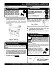
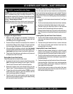
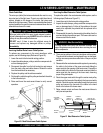
Applying an External Load
The Night-Hawk LT-12 Series Light Tower is available with two
auxiliary output receptacles (Figure 18). The upper most
receptacle (twist-lock) located at the front of the light tower can
provide 240 VAC at 25 amps. The bottom receptacle is a GFCI
receptacle which can supply 120 VAC at 15 amps.
Figure 18. 120/240 VAC Output Receptacles
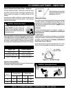
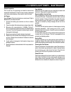
Testing the 120 VAC GFCI Receptacle
Pressing the
reset
button resets the GFCI receptacle after being
tripped. Pressing the "
Test Button
" (See Figure 19) in the center
of the receptacle will check the GFCI function. Both receptacles
should be tested at least once
a month.
NEVER grab or touch a live power
cord with wet hands, the possibility
exists of electrical shock,
electrocution, and even death!
POWER
CORD
(POWER ON)
WET
HANDS
Figure 19. GFCI Test Button
DANGER - Electric Shock Hazards