


LT-12 SERIES LIGHT TOWER — OPERATION MANUAL — REV. #1 (08/15/08) — PAGE 17
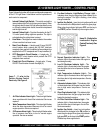
1. Internal Cabinet Light Switch – This switch controls the
internal cabinet light for the light tower control panel. When
the cabinet door is raised, the light will automatically come
on. When the cabinet door closes, the switch is depressed
and the light turns off.
2. Internal Cabinet Light – Provides illumination for the LT-
12 control panel during nighttime operation. The light is
activated when the cabinet door is raised.
3. Hour Meter – This digital hour meter indicates the number
of hours machine has been in use.
4. Main Circuit Breaker – A double-pole 25 amp, ON/OFF
circuit breaker which protects the 240 VAC twist-lock
receptacle from overload. In addition it allows voltage to be
supplied to the GFCI receptacle and 15 amp breakers (4).
5. GFCI Receptacle Circuit Breaker – A single-pole, 15
amp, ON/OFF circuit breaker which protects the GFCI
receptacle from overload.
6. Flood Light Circuit Breakers – A single-pole, 15 amp,
ON/OFF circuit breaker for each floodlight (4).
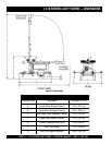
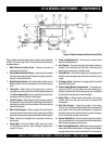
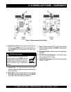
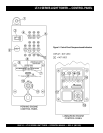
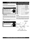
Figure 5 shows the location of the basic control panel components
for the LT-12 Light Tower. Listed below is a brief explanation of
each control or component.
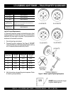
Items 7 - 11 refer to the
Perkins Engine Control
Panel only. See Figure 5.
7. Air Filter Indicator Alarm Light – This alarm light flashes
when a problem with the air filter is detected. Service as
required.
8. Water Temperature Alarm Light – This alarm light flashes
when the water temperature becomes to hot for normal
engine operation. Service as required.
9. Oil Pressure Alarm Light – This alarm light flashes when
the oil pressure has fallen to low for normal engine
operation. Service as needed.
LT-12 SERIES LIGHT TOWER — CONTROL PANEL
10. Pre-Heat Indicator Light/Battery Charge Light –
Indicates when the glow plugs have been heated up for
starting the engine. If the light is flashing, a low battery
charge is detected.
11. Ignition Key Switch – Insert key into ignition switch and
turn clockwise to the ON position to warm the glow plugs.
When glow plug indicator light goes OFF, turn the key to
the START position. Release key when engine starts.
Items 12 - 18 refer to the
Lombardini Engine
Control Panel only. See
Figure 5.
12. Normal Operation Indicator Light – This
indicator light is illuminated when the engine is
functioning normally.
13. Low Oil Shutdown Indicator Light – This
indicator light is illuminated when the engine
has shut down due to low oil pressure. Service
as needed.
14. High Temperature Indicator Light – This
indicator light is illuminated when the engine has
shut down due to high water temperature. Service
as needed.
15. Alternator Indicator Light – This indicator light
is illuminated when the engine has shut down
due to high water temperature. Service as
needed.
16. Glow Plug Indicator Light – This indicator light
is illuminated when the glow plugs have been
heated for starting the engine.
17. Air Filter Restriction Indicator Light – This
indicator light is illuminated when the engine
has shut down due to blockage in the air filter.
Service as needed.
18. Ignition Key Switch – Insert key into ignition
switch and turn clockwise to the ON position to
warm the glow plugs. When glow plug indicator
light goes OFF, turn the key to the START position.
Release key when engine starts.
OK