


PAGE 14 — LT-12 SERIES LIGHT TOWER — OPERATION MANUAL — REV. #1 (08/15/08)
LT-12 SERIES LIGHT TOWER — COMPONENTS
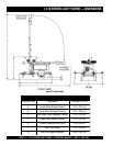
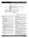
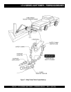
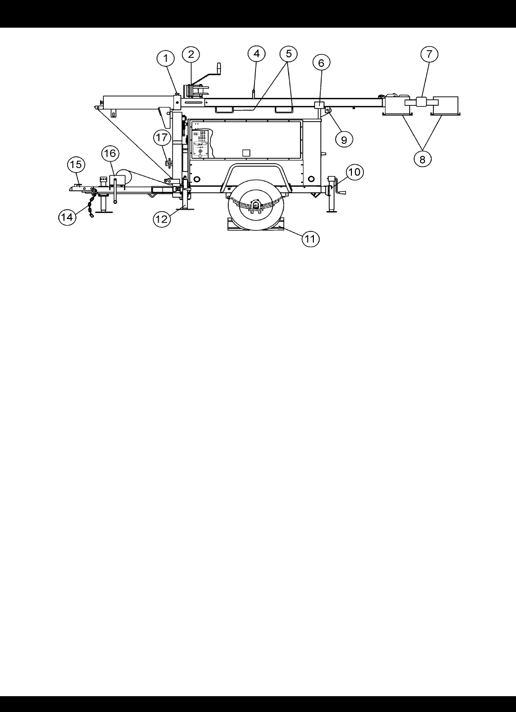
Figure 3 and 4 shows the location of the controls and components
for the LT-12 Series Light Tower. The functions of each control is
described below:
1. Mast Rotation Locking Knob – Unscrew this knob to
release mast for rotation.
2. Vertical Mast Extension Winch – Use this winch to extend
the mast to the desire height. Maximum height is approxi-
mately 31.5 feet (9.6 meters).
3. Mast Rotation Handle – Grip this handle to rotate mast to
desired position. To lock mast tighten mast rotation locking
knob.
4. Lifting Bail – When lifting of the light tower by crane is
required, use this lifting bail. Note: this lifting bail is balanced
for a
fully configured
light tower; removal of any light tower
components will un-balance the lifting bail.
5. Forklift Pockets – When lifting of the light tower is required,
use these fork lift pockets to lift the light tower. Remember to
insert the forks of the fork lift a minimum of 24 inches into the
mast fork lift pockets.
6. Mast Cradle Support – When towing of the light tower is
required, place the tower mast into the cradle support. Make
sure tower release pin has been inserted and mast is locked.
7. T-Bar – Allows the floodlights to be mounted vertically or
horizontally.
8. Flood Light – 1000 watt "Metal Halide" type bulb with a
110,000 lumens capacity. Light coverage is typically be-
tween 5 to 7 acres.
Figure 3. Major Components (Control Panel Side)
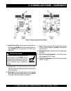
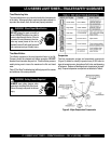
9. Tower Lock/Release Pin – Pull this pin to release tower
mast from cradle support.
10. Jack Stands – There are two trailer jack stands, which are
located at the front and rear of the trailer. Use these 2 jack
stands to level and support the light tower.
11. Chock Blocks – Place these blocks (not included as part of
the light tower package) under each trailer wheel to prevent
rolling.
12. Outrigger Jacks – Use these 2 outrigger jacks to level and
support the light tower.
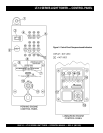
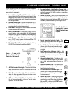
13. Control Panel/ Ballast Compartment – This panel con-
tains the ON/OFF circuit breakers for each flood light. In
addition, located behind the control panel are the ballasts
and electrical components for each floodlight.
14. Safety Chain – Always attach safety chain to the towing
vehicle. Never tow the light tower with the safety chain
unattached.
15. Ball Hitch Coupler – Attach this coupler to the towing
vehicle. Use only the specified ball diameter as indicated on
your coupler. Use of any other ball diameter will create an
extremely dangerous condition which can result in separa-
tion of the coupler and ball or ball failure.
16. Vertical Mast Winch – Use this winch to raise the mast the
to the vertical position. Once mast is in the full vertical position
the locking pin engages automatically.
17. Mast Locking/Release Pin – Pull this pin to start placing the
tower mast in the vertical position.
Locking pin automatically
engages when tower mast has reached full vertical position.