


12
OPERATION
2. Connect the tool to an appropriate hydraulic power source.
Follow the Hydraulic Hose Connection safety guidelines and
instructions in this section. If possible, use the hydraulic power
source you plan to use for crimping.
3. Place the die load tester between the blank (test) dies.
4. Actuate the tool and read the value shown on the load tes-
ter indicator. The force should be 10–12 tons (9072–10,886
kg), depending on the pressure from the hydraulic power
source.
5. If the indicated value is low and the system pressure relief
valve setting is greater than 1650 psi (114 bar), adjust the
relief valve on the CT to get the correct die load.
If the indicated value is high, adjust the relief valve on the CT
to get the correct die load.
6. When the value is within the acceptable range, turn the
hydraulic system control valve off and disconnect the hoses
from the tool.
7. Follow the Die Installation instructions at the beginning of
this section to remove the blank dies and install the proper
crimping dies.
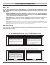
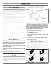
OC/CC SETTING
Check the open-center/closed-center (OC/CC) setting on the
tool. The current setting is easily determined by looking at the
gap between the adapter and the cylinder, see Figure 5-1.
• open center - no gap
• closed center - approximately ¼-inch (6.4-mm) gap
If the setting is not correct for your hydraulic system, follow
the instructions in this section, OC/CC Adjustment, to make
the change.
DIE CHECK
Make sure the dies installed in the tool match the sleeve or
connector to be crimped. If not, follow the instructions in this
section, Die Installation.
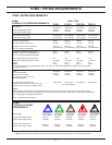
CHECK POWER SOURCE
Using a calibrated owmeter and pressure gauge, check the
hydraulic power source at the tool’s input port. Make sure
the system maintains an operating ow in the range of 3-9
gpm/11-34 lpm within a pressure range of 1650-2000 psi
/114-140 bar.
The hydraulic uid temperature should be at least 80°F/27°C
for this test.
CONNECT HOSES
1. Wipe all hose couplers with a clean, lint-free cloth before
making connections.
2. Connect hoses from the hdyraulic power source to the tool
ttings or quick disconnects. It is good practice to connect the
return hose rst and disconnect it last to minimize or eliminate
trapped pressure within the wrench.
3. Observe the ow indicators stamped on the main body
assembly and the hose couplers to ensure that the ow is
in the proper directions. The female couple on the tools “IN”
port is the inlet (pressure) coupler.
Note:
If the uncoupled hoses are left in the sun, pressure
increase within the hoses can make them difcult to
connect. Whenever possible, connect the free ends of
the hoses together.
OPERATION
Observe all safety precautions when operating the tool. Read
Safety and Hydraulic System Requirements, before operating
the tool for the rst time.
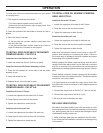
CONDUCTOR PREPARATION
1. If the conductor is insulated, remove the insulation from
the end of the conductor.
Use an insulation stripping tool. If a stripping tool is not avail-
able, carefully shave the insulation from the cable.
Be sure not to nick or cut the strands of the conductor.
2. Remove any oxide or foreign matter from the exposed
conductor. A bright, shiny surface is required for a good con-
nection. Do not wire-brush tin-plated copper conductors or
tinned connectors.
STARTUP
1. Move the hydraulic system control valve to the ON
position.