4
3
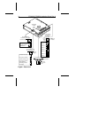
SCSI ID = 0
SCSI ID = 1
SCSI ID = 2
SCSI ID = 3
SCSI ID = 7
SCSI ID = 4
SCSI ID = 5
SCSI ID = 6
MSB
2
1
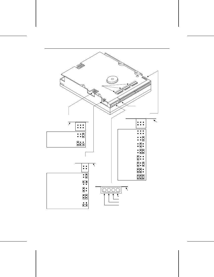
J5. SCSI ID
jumper block
J4. Interface
connector (pin 1)
Circuit
board
Circuit
board
J3. DC power connector
+5V
+5V return
+12V return
+12V
1
2
3
4
Ground
Signal
6
5
J9. Active/passive
termination jumper block
Circuit board
+2.85V to 110 ohms
3
4
1
2
5
6
LSB
Terminating
resistor
packs
(pin 1)
Circuit board
Power and ground to
220/330 ohms
J6. Terminator power
source jumper block
From SCSI connector
1
2
3
4
From power connector
and to SCSI bus
From power connector
Terminating resistors
not installed
To SCSI connector only
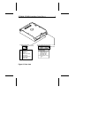
Figure 1. Back view
6 ST3390N, ST3655N Installation Guide, Rev. A


