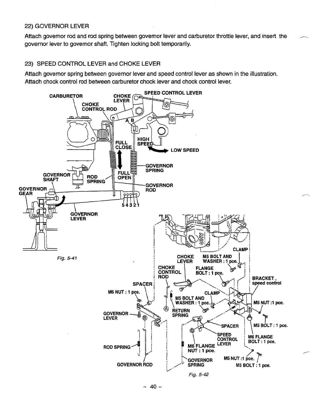
22)
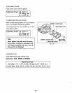
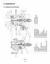
GOVERNOR LEVER
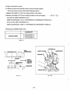
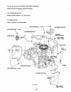
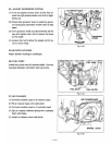
Attach governor rod and
rod
spring between governor lever and carburetor throttle lever, and insert the
,-.
governor lever to governor shaft. Tighten locking bolt temporarily.
23)
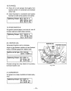
SPEED CONTROL
LEVER
and
CHOKE
LEVER
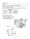
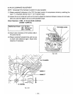
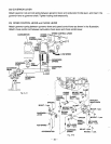
Attach governor spring between governor lever and speed control lever as
shown
in
the illustration.
Attach chock control
rod
between carburetor chock lever and chock control lever.
Fig.
5-41
i
I
I
CHOKE
M5
BOLT
AND
'.
I
~G~~ERNOR
M5
NUT
:1
pee.
GOVERNOR
ROD
/
SPRING
M5
BOLT
:
1
pce.
Fig-
5-42
-
40-
CONTROL
ROD
SPRING
M6
FLANGE
LEVER
NUT
:
1
pce.
M6
FLANGE
BOLT
:
1
pce.


