2)
PISTON
and CONNECTING
ROD
(1)
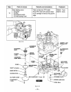
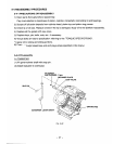
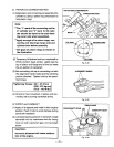
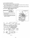
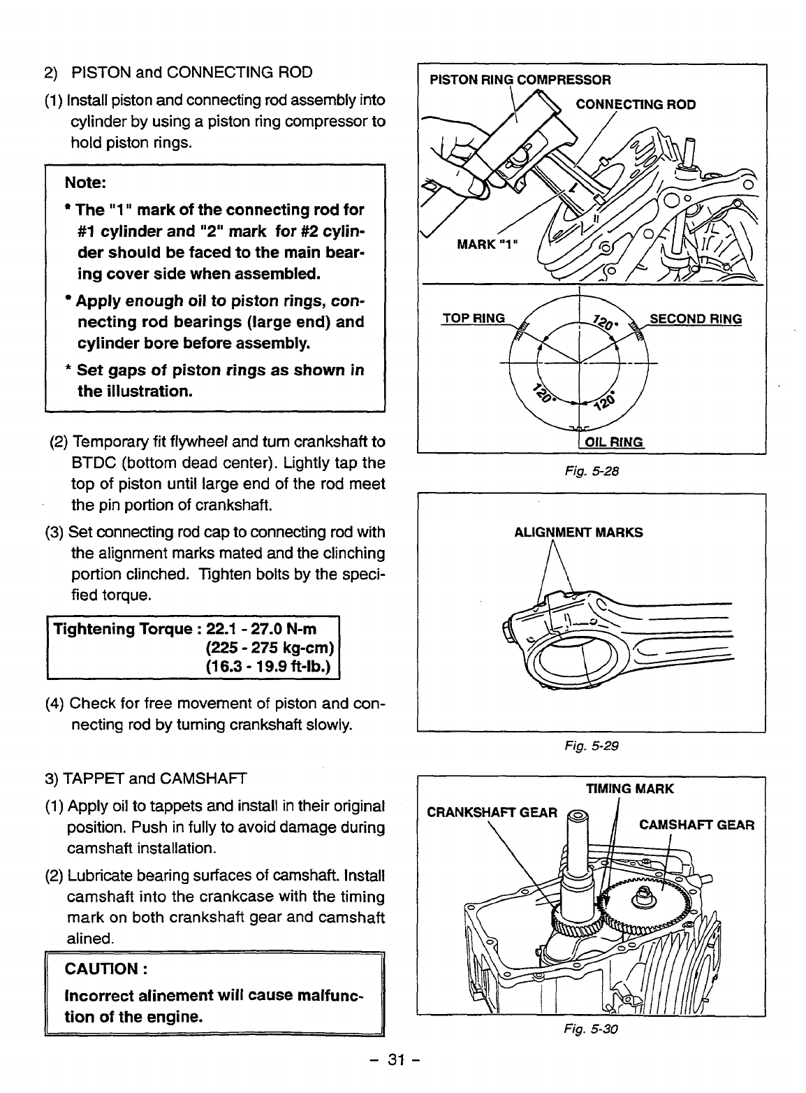
Install piston and connecting rod assembly into
cylinder by using a piston ring compressor to
hold piston rings.
Note:
The
"1
'I
mark
of
the
connecting
rod
for
#I
cylinder and
"2"
mark for
#2
cylin-
der
should
be
faced to the main bear-
ing cover side when assembled.
Apply
enough
oil
to piston rings,
con-
necting rod bearings (large end) and
cylinder bore before
assembly.
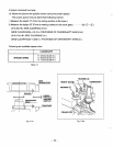
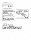
the illustration.
*
Set
gaps of piston rings
as
shown
in
:2)
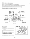
Temporary
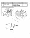
fit flywheel and
turn
crankshaft
to
BTDC
(bottom dead center). Lightly tap the
top
of
piston until large end
of
the rod meet
the pin portion
of
crankshaft.
(3)
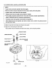
Set connecting rod cap to connecting rod with
the alignment marks mated and the clinching
portion clinched. Tighten
bolts
by the speci-
fied torque.
Tightening Torque
:
22.1
-
27.0
N-m
(225
-
275
kg-cm)
(1
6.3
-
19.9
ft-lb.)
(4)
Check for free movement
of
piston and con-
necting rod
by
turning crankshaft
slowly.
3)
TAPPFT
and
CAMSHAFT
(1)
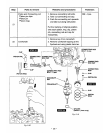
Apply oil to tappets and install in their original
position. Push in fully to avoid damage during
camshaft installation.
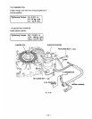
(2)
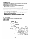
Lubricate
bearing surfaces
of
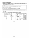
camshaft. Install
camshaft into the crankcase with the timing
mark on both crankshaft gear and camshaft
alined.
CAUTION
:
Incorrect
alinement
will cause malfunc-
tion
of
the
engine.
PISTON RING COMPRESSOR
\A
CONNECTING ROD
Fig.
5-28
ALIGNMENT MARKS
n
Fig.
5-29
TIMING
MARK
CRANKSHAFT
GEAR
\
//
CAMSHAFTGEAR
Fig.
5-30
-
31
-


