


Pelco Manual C554M-A (5/98) 21
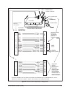
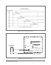
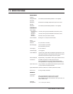
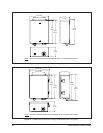
Figure 7. AC Input and Fuse Values
F3
F2
F1
POWER OUTPUT
INPUT P/T
VAC VAC
CX9024RX
CX9024RXI
*12VDC Camera
options use a
1/2ASB fuse
value in this
position in place
of the 2/10's
value.
*CX9024RXI-12V
*CX9024RX-12V
CX9024RX-PP
CX9024RXI-PP
CX9224RX
CX9224RX-PP
CX9224RXI
CX9224RXI-PP
*CX9224RXI-12V
CX9115RX
CX9115RX-PP
CX9115RXI
CX9115RXI-PP
1ASB
2/10ASB
*1/2ASB
NOT
USED
.5A/250V
5X20MM
.1A/250V
5X20MM
2/10ASB
1/10ASB
1/2ASB
1A
1ASB
2/10ASB
2/10ASB
120VAC
24VAC
P/T OUT
IN
P/T
CAMERA
PC BOARD
230VAC
IN
24VAC
P/T OUT
230VAC
IN
230VAC
P/T OUT
24VAC
IN
24VAC
P/TOUT
120VAC
IN
120VAC
P/T OUT
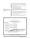
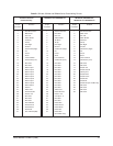
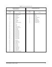
A P P L I C A B L E M O D E L S
Additional
combinations
of equip-
ment options
are possible
depending
on custom-
er need &
availability.
This listing
covers the
most used
and/or the
most available
type units &
their options.
NOT
USED
NOT
USED
3A
CX9024RX/220
CX90224RX-PP220
CX9220RX
CX9220RX-PP
CX9220RXI
CX9220RXI-PP
3AG TYPE
FUSE
3AG TYPE FUSE
3AG TYPE FUSE
3AG TYPE
FUSE
*The CX9224
option with
12 VDC camera
uses one fuse
in the F3
position. It is a
3A fuse not a
3ASB fuse.
Fuse positions
F1 and F2 are
not used.
**
**
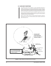
AC INPUT DESIGNATIONS
1. AC HIGH
2. GROUND
3. AC LOW
F1
F2 FUSE
F3
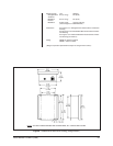
SW 1 SHOWN IN THE “LONG” POSITION
**
SW1 SHOWN IN THE “SHORT” POSITION
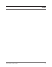
P2
P1
PC BOARD
TRANSMITTER: F1 2/10 ASB, 3AG
RECEIVER FUSE VALUES: SHOWN BELOW
BNC CONNECTORS
37-PIN AMP CONNECTOR
POWER INPUT
FOR REV K BOARDS, THE SW1 SWITCH
POSITIONS SHOWN ABOVE ARE JUST
REVERSED, THAT IS, “SHORT” IS “LONG”
AND “LONG” IS “SHORT”.