


10 Pelco Manual C554M-A (5/98)
3.0 INSTALLATION
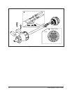
3.1 MOUNTING THE CX9000
1. Determine the location where the CX9000 is to be installed.
2. Using the CX9000 box as a template, mark the hole pattern on the mounting
surface. Drill holes in the mounting surface.
3. Attach the CX9000 securely with four fasteners of appropriate length (not sup-
plied.)
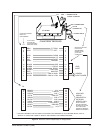
3.2 VIDEO
Receiver Video Input
Connect the video input to the BNC connector marked IN on the CX9000 box. The
input video connector accepts the signal from the camera serviced by the receiver.
The receiver provides 75 ohm cable termination and an isolation amplifier to pre-
vent the control pulse train from being fed to the camera.
Refer to Table A. Video Coaxial Cable Wiring Distances.
Receiver Video Output
Connect the video output to the BNC connector marked OUT on the CX9000 box.
The output video connector is connected to the corresponding controller video input
connector. Proper termination of this cable is vital to the operation of the equipment.
Although loop-through connections in this cable are permissible, power splitters or
line amplifiers should not be used.
Refer to Table A. Video Coaxial Cable Wiring Distances.
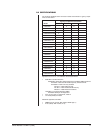
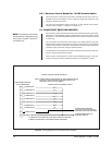
Table A. Video Coaxial Cable Wiring Distances
Cable Type* Maximum Distance
RG59/U 750 ft (229 m)
RG 6/U 1,000 ft (305 m)
RG11/U 1,500 ft (457 m)
* Minimum cable requirements:
75 ohms impedance
All-copper center conductor
All-copper braided shield with 95% braid coverage
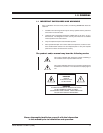
NOTE:
When installing the
CX9000 to a wall outdoors, seal the
bolt holes with an appropriate seal-
ant. Apply the sealant around the
bolt holes between the unit and the
mounting surface. This will prevent
possible water damage to the wall
caused by rainwater leaking
through the mounting bolt holes.
(This may only be a problem when
the mounting bolts go completely
though the wall.)
Proceed to Section 3.3, CONNECTOR ASSEMBLY