


18 Pelco Manual C554M-A (5/98)
3.5 AUXILIARY FUNCTIONS
The Coaxitron
®
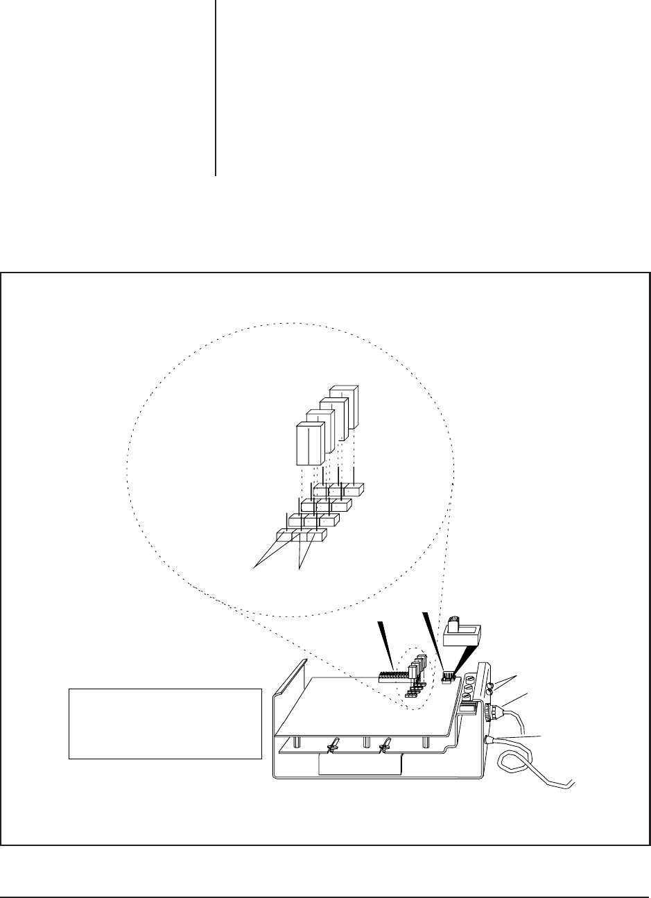
receiver, using a Revision J or newer receiver/driver PC board, is
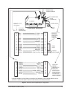
capable of operating up to four remotely activated auxiliary functions. Each auxil-
iary output may be individually converted at the receiver for momentary or latching
operation. Refer to Figure 4 to set jumpers for auxiliary functions. When in the latch-
ing mode, activating the same AUX function will toggle the function from on to off.
The AUX outputs are buffered to provide a continuous 10 VDC at 25 mA to drive
small relays, lamps or other external devices. Refer to Figures 5 and 6 for examples
of typical circuits used for auxiliary functions.
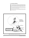
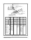
Figure 5 shows a typical connection using the latching command to operate an
external device for auto iris or manual iris operation (AUX 1 latches manual iris and
AUX 2 latches auto iris.)
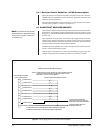
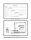
Figure 4. Jumper Settings on the Receiver/Driver PC Board
FOR REVISION K (REV. K) BOARDS,
SW1 POSITIONS ARE REVERSED;
THAT IS, THE POSITION SHOWN
ABOVE IS THE “LONG” POSITION
FOR REV. K BOARDS.
**
AUXILIARY JUMPER
SETTINGS ON THE
COAXITRON
®
RECEIVER
BOARD. JUMPERS ARE
SHOWN IN THE MOMENTARY
“POSITION” OR “MODE”.
COAXITRON
®
RECEIVER
LATCHING
MOMENTARY
JP1 AUX1
JP2 AUX2
JP3 AUX3
JP4 AUX4
P 1
P 2
SW1 ** SHOWN IN THE
“SHORT” POSITION
BNC CONNECTORS
37-PIN
CONNECTOR
POWER INPUT
PC BOARD