


5
LA000507G © 2006 Navman New Zealand. All rights reserved. Proprietary information and specications subject to change without notice.
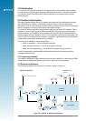
2.3 Major components of the Jupiter 20
LNA (Low Noise Amplier): This amplies the GPS signal and provides enough gain for the
receiver to use a passive antenna. A very low noise design is utilised to provide maximum
sensitivity.
Bandpass lter (1.575 GHz): This lters the GPS signal and removes unwanted signals caused by
external inuences that would corrupt the operation of the receiver.
RFIC (Radio Frequency Integrated Circuit): The RFIC (SiRFstarII GRF 2i/LP) and related
components convert the GPS signal into an intermediate frequency and then digitise it for use by
the baseband processor.
TCXO (Temperature Compensated Crystal Oscillator): This highly stable 24.5535 MHz oscillator
controls the down conversion process for the RFIC block. Stability in this frequency is required
to achieve a fast TTFF.
Baseband processor: The SiRFstarII GSP 2e/LP processor is the main engine of the GPS
receiver. It runs all GPS signal measurement code, navigation code, and other ancillary routines,
such as power saving modes. The normal I/O of this processor is via the two serial ports.
Flash memory: The Flash memory stores software and also some long term data.
RTC (Real Time Clock) crystal: The 32 kHz crystal operates in conjunction with the RTC inside
the baseband processor. It provides an accurate clock function when main power has been
removed, if the battery backup is connected.
Reset generator: There are two voltage threshold reset generators in the Jupiter 20. The rst
provides a reset to the baseband block if the main power drops below a low limit threshold.
The second shuts off the supply to the RTC in case the backup battery drops below a lower
threshold. This is used to compensate for a slow SiRF rise‑time backup voltage.
Regulators: The regulators provide a clean and stable voltage supply to the components in the
receiver.
DR (Dead Reckoning) components: The Jupiter 20D has additional components allowing direct
connection to a turn rate gyro. The gyro input takes the form of a high resolution ADC (Analogue
to Digital Converter), where the analogue signal is digitised and prepared for use by the
SiRFDRive DR software running in the baseband processor.
2.4 Physical characteristics
The Jupiter 20 receiver is packaged on a miniature printed circuit board with a metallic RF
enclosure on one side. The standard or DR conguration must be selected at the time of
ordering and is not available for eld retrotting.
A lead‑free RoHS compliant product has been available since the end of 2005.
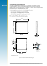
2.5 Mechanical specication
The physical dimensions of the Jupiter 20 are as follows:
length: 25.4 mm ± 0.1 mm
width: 25.4 mm ± 0.1 mm
thickness: 3.0 mm max
weight: 4.0 g max
Refer to Figure 8‑1 for the Jupiter 20 mechanical drawing.
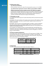
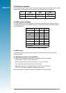
2.6 External antenna surface mount pads
The RF surface mount pad for the external antenna has a characteristic impedance of 50 ohms.
2.7 I/O and power connections
The I/O (Input Output) and power connections use surface mount pads with edge plating around
the edge of the module.