


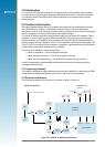


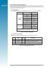
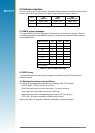


Figure 2-1: Jupiter 20 module architecture
LNA
bandpass
lter
TCXO
baseband
processor
RFIN
ADC
GYRO IN
active or passive antenna
controls/
GPIO
UART
ports
RTC crystal
Flash memory
AD [0‑18] D [0‑15]
CTRL
brown out
detector
1.8 V
regulator
2.8 V
regulator
Module architecture
RFIC
DR Modules only
forward/
reverse
wheel
ticks
bias T
V_ANT
input
ORing
circuit
PWRIN
PWRIN
PWRIN
VBATT
4
LA000507G © 2006 Navman New Zealand. All rights reserved. Proprietary information and specications subject to change without notice.
1.0 Introduction
The Jupiter 20 GPS receiver module is a very small surface mount receiver that is intended
as a component for OEM (Original Equipment Manufacturer) products. The module provides
a 12‑channel receiver that continuously tracks all satellites in view and provides accurate
positioning data.
2.0 Technical description
The highly integrated digital receiver incorporates and enhances the established technology
of the SiRFstarIIe/LP chipset. It is designed to meet the needs of the most demanding
applications, such as vehicle tracking in dense urban environments. The interface conguration
allows incorporation into many existing devices and legacy designs.
The Jupiter 20 receiver decodes and processes signals from all visible GPS satellites. These
satellites, in various orbits around the Earth, broadcast RF (radio frequency) ranging codes,
timing information, and navigation data messages. The receiver uses all available signals to
produce a highly accurate navigation solution. The 12‑channel architecture provides rapid TTFF
(Time To First Fix) under all start‑up conditions. Acquisition is guaranteed under all initialisation
conditions as long as visible satellites are not obscured.
The Jupiter 20 is available in three congurations:
• Jupiter 20 (standard) – GSW2.3 navigation software
• Jupiter 20S (high sensitivity) – with XTrac navigation software
• Jupiter 20D (Dead Reckoning) – with SiRFDRive software and gyro interface
Protocols supported are selected NMEA (National Marine Electronics Association) data
messages and SiRF binary.
2.1 Product applications
The module is designed for high performance and maximum exibility in a wide range of OEM
congurations including hand‑helds, sensors, and in‑vehicle automotive products.
2.2 Receiver architecture
The functional architecture of the Jupiter 20 receiver is shown in Figure 2‑1.