


Mechanical - XTB
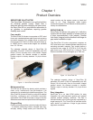
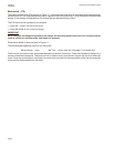
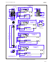
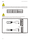
The XTB is shown in Figure 2.2. It comprises the forcer and the thrust rod. With the addition of thrust rod supports and a
linear bearing a moving forcer solution can be implemented.
The XTB forcer can be mounted by two methods. T -slots are available in the top of the forcer but more normally the
forcer is mounted to bearing carriages to allow the use of a linear bearing. Dimensional details for both are shown in
Figure 2.2. The recommended tightening torque for the fixings are:
M4 bearing to forcer 4 Nm M6 T-nut 10 Nm
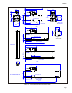
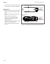
The thrust rod can be mounted using thrust rod supports (part number 400 885 361). The thrust rod support comprises
a split clamp with two M10 pinch bolts.
All torque figures are non-lubricated i.e. no thread lock.
As the XTB has a moving forcer it is supplied with highly flexible cables suitable for continuous flexing operation. In
order to achieve the best reliability and life from these cables it is advised that some form of cable management system
is used. Typically, this will be an energy chain mounted parallel to the direction of motion. Always follow the
manufacturers recommendations when installing cables into energy chains. In particular:
•
Observe cable minimum bend radius requirements (see Appendices).
•
Never allow the cable to be under tension within the energy chain.
•
Physically separate cables within the energy chain to prevent premature failure due to abrasion.
•
Never cross cables within the energy chain.
•
Be careful to prevent the cable from twisting or becoming kinked during installation into the energy chain.
Page 6
Chapter 2 ServoTube 38 Installation Guide
Installation