Mechanical - XTA
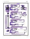
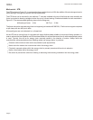
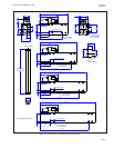
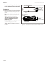
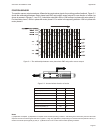
The outline drawing of the XTA is shown in Figure 2.1. It comprises the forcer with an integrated plastic sleeve bearing
and the thrust rod. The integrated bearing acts as a guide for the moving thrust rod. It is not intended to withstand side
loading. If side loading is expected then it is advised that an external bearing is fitted.
The XTA forcer can be mounted by two methods.
• Using the T -slots in the top of the forcer.
• Using M6 fixings (4 off) on the end flange.
IMPORTANT
When using the end flange fixing method, the fixings and mounting plate must be of a non- ferrous material
such as aluminum, stainless steel, and plastic for example.
Dimensional details for both are given in Figure 2.1.
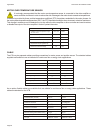
The recommended tightening torque for the fixings are:
M6 end flange 9 Nm M6 T-nut 10 Nm (both non lubricated i.e. no thread lock)
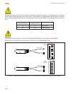
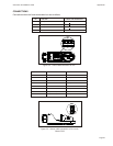
The thrust rod has optional male and female threaded connections at each end. These are intended to interface to a
number of standard accessories. The thrust rod has an external circlip at each end to restrain the thrust rod within the
forcer. These are not intended as "hard stops" to prevent over-travel and it is the responsibility of the User to prevent the
thrust rod from being ejected from the forcer.
Page 4
Chapter 2 ServoTube 38 Installation Guide
Installation