


ABS <2WD> -
On-vehicle Service
35B-20
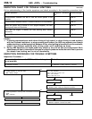
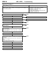
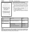
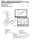
Inspecting Waveforms With An Oscilloscope
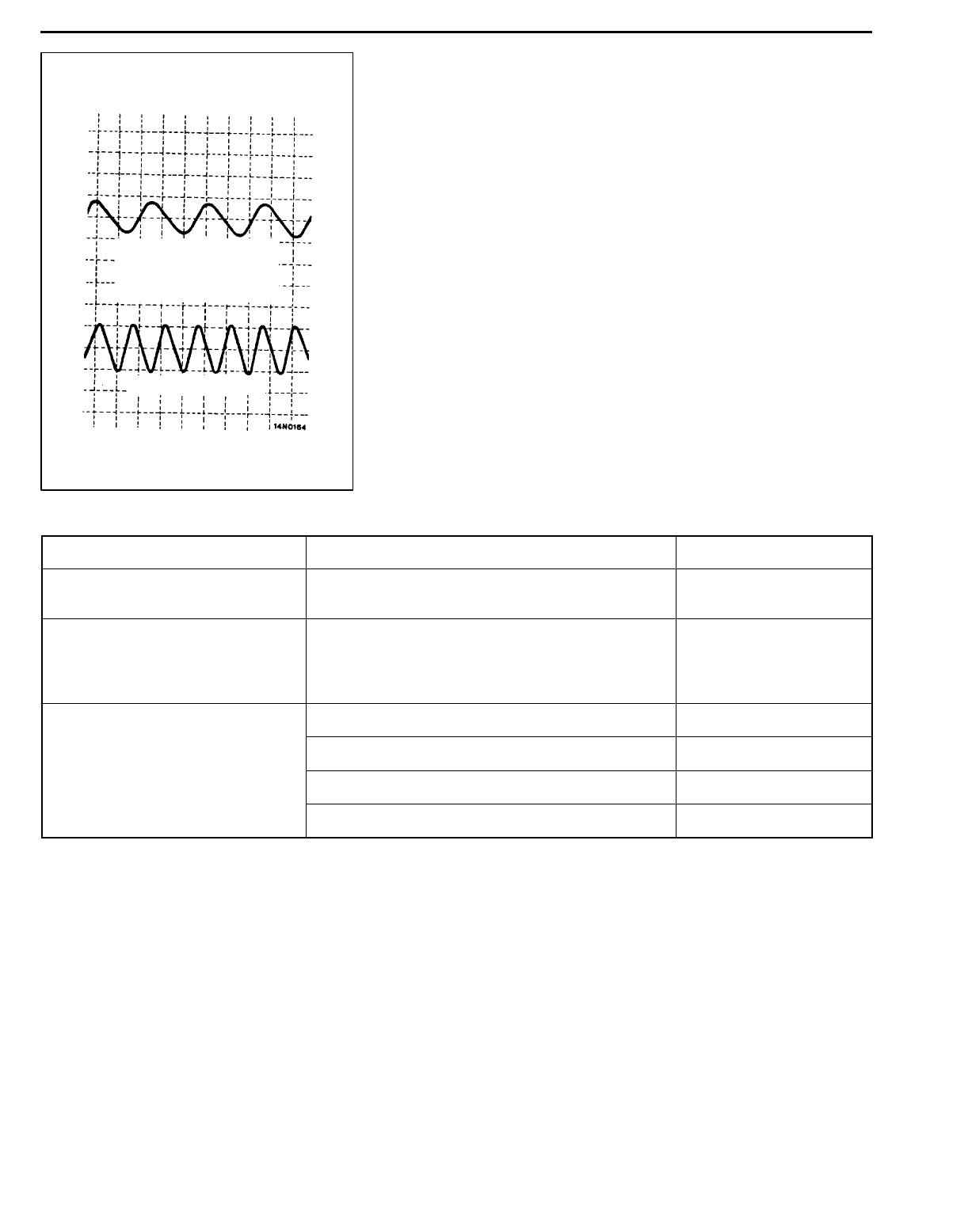
Use the following method to observe the output voltage
waveform from each wheel sensor with an oscilloscope.
D Start the engine, and rotate the front wheels by engaging
1st gear (vehicles with manual transmission) or D range
(vehicles with automatic transmission). Turn the rear
wheels manually so that they rotate at a constant speed.
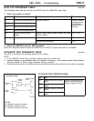
NOTE
1. Check the connection of the sensor harness and
connector before using the oscilloscope.
2. The waveform measurements can also be taken while
the vehicle is actually moving.
3. The output voltage will be small when the wheel speed
is low, and similarly it will be large when the wheel speed
is high.
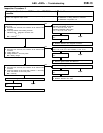
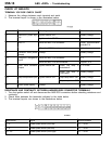
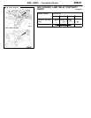
Points In Waveform Measurement
Symptom Probable causes Remedy
Too small or zero waveform
amplitude
Faulty wheel speed sensor Replace sensor
Waveform amplitude fluctuates
excessively (this is no problem if
the minimum amplitude is 100 mV
or more)
Axle hub eccentric or with large runout Replace hub
Noisy or disturbed waveform Open circuit in sensor Replace sensor
Open circuit in harness Correct harness
Incorrectly mounted wheel speed sensor Mount correctly
Rotor with missing or damaged teeth Replace rotor
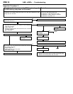
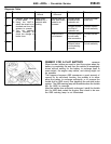
Caution
Because the wheel speed sensor cables move together with the front and rear suspension, they
vibrate greatly when driving over poor road surfaces. As a result, the sensor harnesses should
also be shaken when monitoring of output waveforms of the wheel speed sensors in order to
simulate conditions such as driving over poor road surfaces.
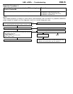
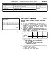
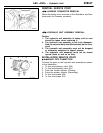
When turning by hand
When idling (5-6 km/h),
1st gear (manual trans-
mission) or Drange (auto-
matic transmission)
10.0 ms/DIV 1 V/DIV