


ABS <2WD> -
Troubleshooting
35B-18
CHECK AT ABS-ECU
35201180229
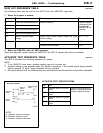
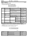
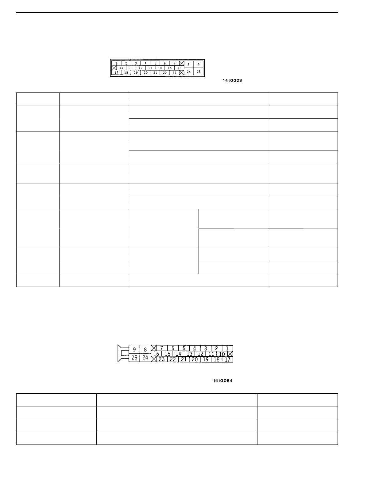
TERMINAL VOLTAGE CHECK CHART
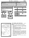
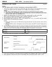
1. Measure the voltage between each terminal and earth.
2. The terminal layout is shown in the illustration below.
Terminal No. Check item Checking requirements Normal condition
4 ABS-ECU power sup- Ignition switch: ON Battery voltage
ply
Ignition switch: START 0V
7 MUT-
II
When the MUT-
II
is connected Serial communication
with MUT-
II
When the MUT-
II
is not connected 1 V or less
9 Solenoid valve power
supply
Always Battery voltage
14 Diagnosis changeover When the MUT-
II
is connected 0V
input
When the MUT-
II
is not connected Approx. 12 V
16 ABS valve transistor
output
Ignition switch: ON When the lamp is
switched off
2 V or less
When the lamp is
illuminated
Battery voltage
18 Stop lamp switch input Ignition switch: ON Stop lamp switch: ON Battery voltage
Stop lamp switch: OFF 1 V or less
25 Motor power supply Always Battery voltage
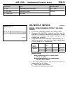
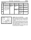
RESISTANCE AND CONTINUITY BETWEEN HARNESS-SIDE CONNECTOR TERMINALS
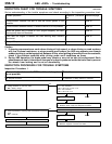
1. Turn the ignition switch off an d disconnect the ABS-ECU connectors before checking resistance an d
continuity.
2. Check them between the terminals indicated in the table below.
3. The terminal layouts are shown in the illustrations below.
Terminal No. Signal Normal condition
1-2 Wheel speed sensor (front left) 1.0 - 1.5 k
W
5-6 Wheel speed sensor (rear left) 1.0 - 1.5 k
W
19 - 20 Wheel speed sensor (front right) 1.0 - 1.5 k
W