


BASIC BRAKE SYSTEM -
Master Cylinder and Brake Booster
35A-17
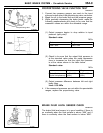
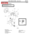
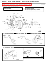
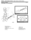
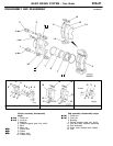
Removal steps
1. Brake pipe connection
2. Brake fluid level sensor connector
3. Master cylinder assembly
"
B
ADPush rod protruding length check and
adjustment
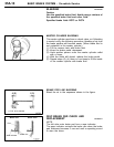
4. Vacuum hose <4D6>
5. Vacuum pipe <4D6>
"
A
A 6. Vacuum hose
(with built-in check valve)
7. Fitting
8. Snap pin
9. Pin assembly
10. Clevis
11. Vacuum switch connector <4D6>
12. Vacuum switch <4D6>
13. Brake booster
14. Sealer
INSTALLATION SERVICE POINTS
"
A
A
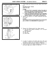
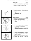
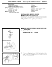
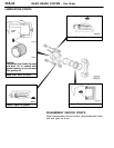
VACUUM HOSE CONNECTION
Insert securely and completely until the vacuum hose at the
engine side contacts the edge of the hexagonal part of the
fitting, and then secure by using the hose clip.
"
B
A
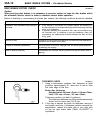
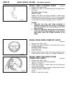
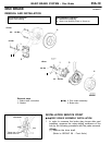
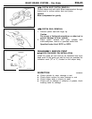
PUSH ROD PROTRUDING LENGTH CHECK AND
ADJUSTMENT
1. Measure dimension A.
Standard value: 9.65 - 9.90 mm
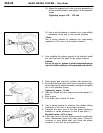
2. If the protruding length is not within the standard value
range, adjust by changing the push rod length by turning
the end of the push rod.
Measuring dimension A
Block gauge
A