


ABS <2WD> -
Troubleshooting
35B-12
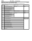
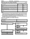
INSPECTION CHART FOR TROUBLE SYMPTOMS
35201140289
Get an understanding of the trouble symptoms and check according to the inspection procedure chart.
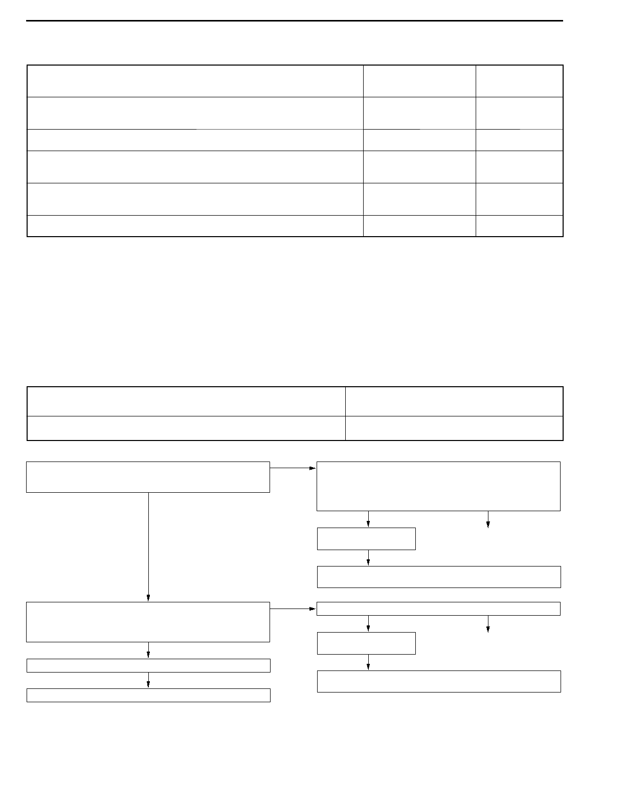
Trouble symptoms Inspection procedure
No.
Reference page
Communication between the MUT-
II
and the whole system is not
possible.
1 35B-12
Communication between the MUT-
II
and the ABS-ECU is not possible. 2 35B-13
When the ignition key is turned to “ON” (engine stopped), the ABS
warning lamp does not illuminate.
3 35B-14
Even after the engine is started, the ABS warning lamp remains
illuminated.
4 35B-15
Faulty ABS operation 5 35B-16
Caution
1. If steering movements are made when driving at high speed, or when driving on road surfaces
with low frictional resistance, or when passing over bumps, the ABS may operate even though
sudden brakingis not being applied.Because of this, whengetting informationfrom the customer,
check if the problem occurred while driving under such conditions as these.
2. During ABS operation, the brake pedal may vibrate or may not be able to be depressed. Such
phenomena are due to intermittent changes in hydraulic pressure inside the brake line to prevent
the wheels from locking and is not an abnormality.
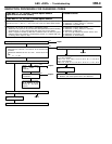
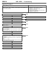
INSPECTION PROCEDURE FOR TROUBLE SYMPTOMS
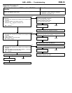
Inspection Procedure 1
Communication between the MUT-
II
and the whole system
is not possible.
Probable cause
The cause may be a malfunction of the power supply circuit or the earth circuit of
the diagnosis connector.
D
Malfunction of diagnosis connector
D
Malfunction of wiring harness or connector
NG
Repair
NG
Replace the MUT-II.
NG
Repair
NG
Check the harness wire, and repair if necessary.
D
Between diagnosis connector and earth
OK
Check the trouble symp-
tom.
OK
Check the trouble symptom.
Measure at the diagnosis connector C-20.
D
Continuity between 4 and body earth, and between 5 and body
earth
OK:
Continuity
NG
Check the following connector:
C-20
OK
NG
Check the harness wire, and repair if necessary.
D
Between power supply an d diagnosis connector
OK
Check the trouble symp-
tom.
Measure at the diagnosis connector C-20.
D
Voltage between 16 and body earth
OK:
Battery voltage
NG
Check the following connectors:
<L.H. drive vehicles>
C-20, C-66, C-63, C-132, C-141
<R.H. drive vehicles>
C-20, C-66, C-62, C-14