


BASIC BRAKE SYSTEM -
Disc Brake
35A-20
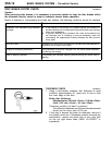
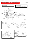
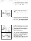
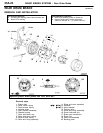
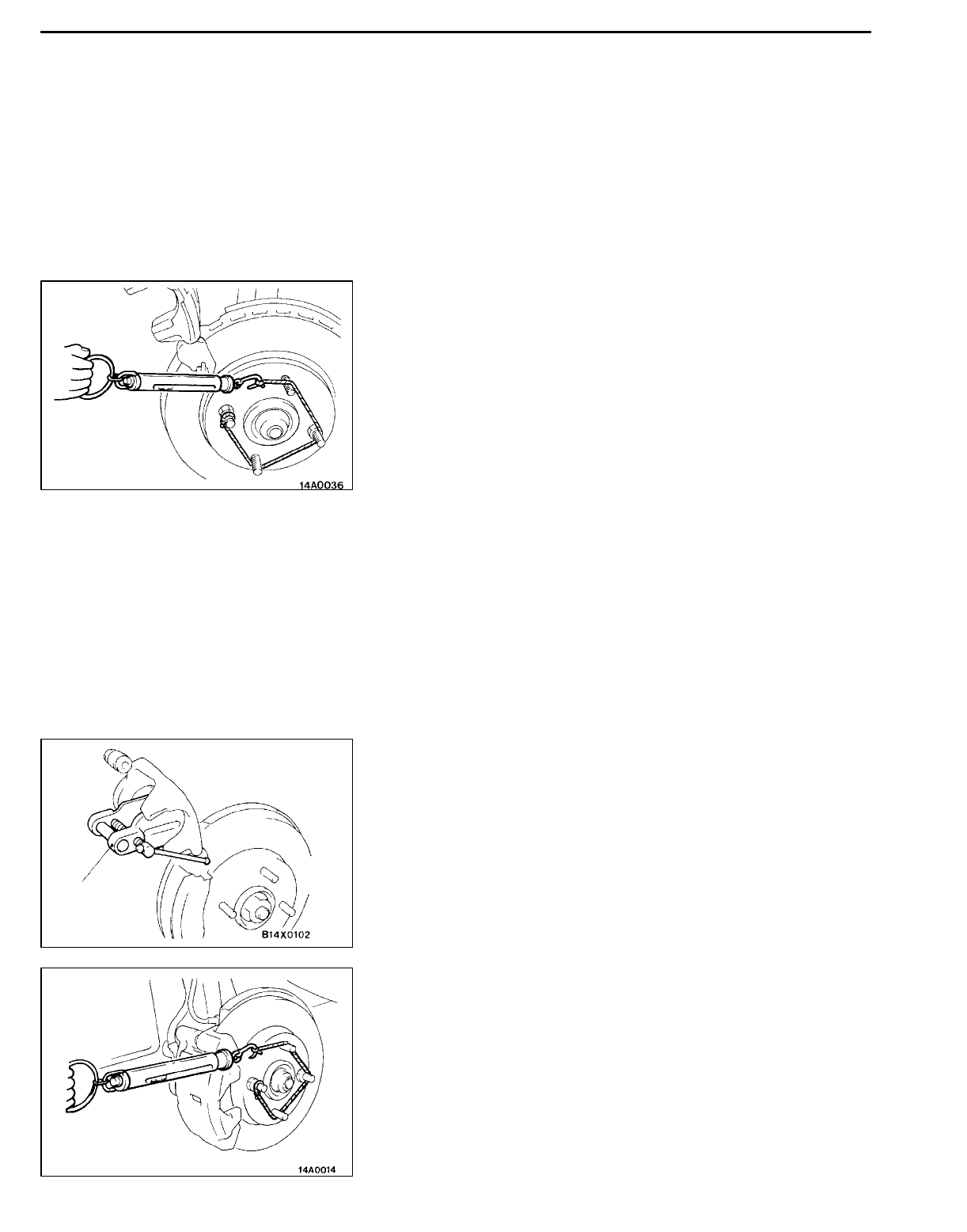
(2) Attach the special tool to the front hub assembly as
shown in the illustration, and tighten it to the specified
torque.
Tightening torque: 196 - 255 Nm
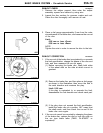
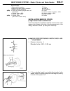
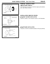
(3) Use a spring balance to measure the rotary-sliding
resistance of the hub in the forward direction.
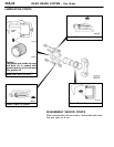
<Rear>
Use a spring balance to measure the rotary-sliding
resistance of the hub in the forward direction.
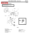
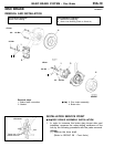
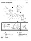
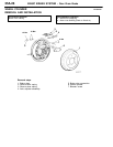
2. After installing the caliper support to the knuckle, install
the pad clips and the pads to the caliper support.
Caution
Do not let any oil, grease or other contamination get
onto the friction surfaces of the pads and brake discs.
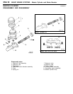
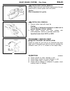
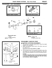
3. Clean piston and insert into cylinder with special tool.
4. Be careful that the piston boot does not become caught
when lowering the caliper assembly, and tighten the guide
pin to the specified torque.
Tightening torque: 74 Nm
5. Start the engine and then depress the brake pedal 2- 3
times.
6. Stop engine.
7. Turn brake disc forward 10 times.
8. Use a spring balance to measure the rotation sliding
resistance of the hub in the forward direction.
9. Calculate the drag force of the disc brake (difference
between of values measured in item 8 and item 1.)
Standard value: 69 N or less
10. If the drag force of the disc brake exceeds the standard
value, disassemble piston and clean piston. Check for
corrosion or worn piston seal, and check the sliding
condition of the lock pin and guide pin.
MB990520