


FFM100 User’s Manual
Page iv Revision 1.2
3.5 Configuring Channel #1 ............................................................................................... 15
3.5.1 Enabling/Disabling Channel #1 ......................................................................... 15
3.5.2 Configuring Channel #1 Engine Instance .......................................................... 15
3.5.3 Configuring Channel #1 Engine Label............................................................... 15
3.5.4 Configuring Channel #1 K-factor ....................................................................... 15
3.5.5 Configuring Channel #1 Temperature Coefficient ............................................. 15
3.5.6 Configuring Channel #1 Data Damping Period ................................................. 16
3.5.7 Resetting the Total Volume Recorded for Channel #1 ...................................... 16
3.5.8 Configuring Channel #1 Temperature Instance ................................................ 16
3.5.9 Configuring Channel #1 Temperature Source ................................................... 16
3.5.10Configuring Channel #1 Temperature Label ..................................................... 16
4 Maintenance ....................................................................................................................... 16
5 Troubleshooting ................................................................................................................. 18
6 Technical Specifications ..................................................................................................... 19
7 Technical Support .............................................................................................................. 20
8 Installation Template .......................................................................................................... 21
9 Maretron (2 Year) Limited Warranty ................................................................................... 22
Table of Figures
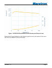
Figure 1 - M1RSP-2R-E8 and M2RSP-2R-E8 Accuracy and Pressure Loss ............................. 3
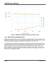
Figure 2 - M4ARP-2-E8 Typical Accuracy and Pressure Loss .................................................. 4
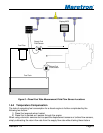
Figure 3 - Diesel Fuel Rate Measurement Fluid Flow Sensor Locations ................................... 5
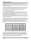
Figure 4 – Fluid Flow Sensor Selection Chart for Diesel Engine Applications ........................... 6
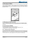
Figure 5 – Mounting the FFM100 .............................................................................................. 9
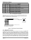
Figure 6 – Fluid flow sensor Connection Diagram ................................................................... 10
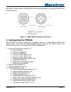
Figure 7 – NMEA 2000
®
Connector Face Views ..................................................................... 11
Figure 8 – Troubleshooting Guide ........................................................................................... 18
Figure 9 – Mounting Surface Template ................................................................................... 21
Table of Appendices
Appendix A – NMEA 2000
®
Interfacing .................................................................................... A1