


FFM100 User’s Manual
Page 6 Revision 1.2
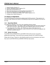
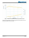
into account will result in the fuel consumption being underestimated. In fact, without
compensating for temperature, if the engine were consuming no fuel, the return fuel flow rate is
greater than the supply fuel rate, since the fuel is expanded by the engine’s heat as it passes
through the injection system.
The M1RSP-2R-E8, M2RSP-2R-E8, and M4ARP-2-E8 fuel flow sensors feature embedded
temperature sensors, so that the temperature of both the supply and return fuel is sensed and
used in real time by the FFM100 to compensate for the expansion of the fuel due to the
increase in temperature, for the most accurate possible fuel flow measurement.
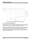
1.6.5 Fuel Flow Sensor Selection
The fluid flow sensors must likewise be sized to accommodate the flow rate of fluid flowing
through the supply and return lines, as opposed to the net fuel consumption used by the
engine. If too small a fuel flow sensor is used, excessive back pressure will occur through the
sensors and the sensor may wear prematurely.
For example, consider the M1RSP-2R-E8 fluid flow sensor, which is rated at a maximum flow
rate of 26.4 GPH (100 LPH). A typical diesel engine will consume 20% of the fuel sent to the
engine, so under this assumption, this fuel sensor will be able to support a diesel engine which
consumes 5.28 GPH (20 LPH).
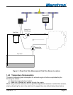
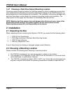
The fluid flow sensor you select must have sufficient range to measure the supply flow rate of
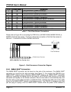
the engine whose fuel consumption you are monitoring. The table in Figure 4 below shows the
maximum fuel supply flow rates that can be sensed by each fuel flow sensor, and approximate
engine power ranges for each fuel flow sensor type. Please consult your engine’s
documentation or contact your engine manufacturer for the maximum supply fuel flow rate
(sometimes called fuel feed rate) for the specific engine whose fuel consumption you wish to
monitor.
Fluid Flow Sensor Flow Rate Range
Approximate
Engine Power
Range
M1RSP-2R-E8 0.53 to 26.4 GPH
2 to 100 LPH
20 to 200 HP
14.9 to 149 kW
M2ESP-2R-E8 4 to 132 GPH
15 to 500 LPH
200 to 1000 HP
149 to 746 kW
M4ARP-2-E8 48 to 396 GPH
180 to 1500 LPH
1000 to 3000 HP
746 to 2237 kW
Figure 4 – Fluid Flow Sensor Selection Chart for Diesel Engine Applications
If you are unable to obtain maximum supply fuel flow rates from the engine manufacturer,
another way to get a good estimate of the engine’s fuel feed rate is to disconnect the fuel
return line from the tank and direct it into a five gallon bucket. Run the engine at maximum
RPM until the bucket is filled, and calculate the return fuel flow rate by dividing the amount of
fuel in the bucket by the amount of time it took to fill the bucket. For instance, if it took 15
minutes (0.25 hour) to fill the five gallon bucket, the return flow rate is: