


FFM100 User’s Manual
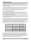
Pin # Signal Name Connection
1 P0 Fluid flow sensor 0 power connection
2 G0 Fluid flow sensor 0 ground connection
3 A0 Fluid flow sensor 0 phase A connection
4 B0 Fluid flow sensor 0 phase B connection
5 C0 Fluid flow sensor 0 phase C connection
6 T0 Fluid flow sensor 0 temperature sensor connection
7 P1 Fluid flow sensor 1 power connection
8 G1 Fluid flow sensor 1 ground connection
9 A1 Fluid flow sensor 1 phase A connection
10 B1 Fluid flow sensor 1 phase B connection
11 C1 Fluid flow sensor 1 phase C connection
12 T1 Fluid flow sensor 1 temperature sensor connection
Table 1 - Fluid Flow Sensor Connections
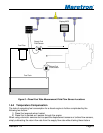
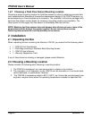
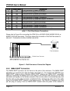
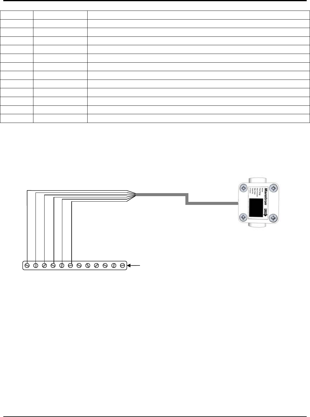
Please refer to Figure 6 for connecting the FFM100 to a M1RSP-2R-E8, M2RSP-2R-E8, or
M4ARP-2-E8 fluid flow sensor. This figure shows the connection of the fluid flow sensor to
channel 0. Connections to other channels are similar.
Fluid flow sensor
FFM100 Screw Terminals
Oran
g
e
B
lack
Red
Blue
White
Green
1 2
P0
G0
5 4 3 6 7 8 9 10 11 12
B0
C0
T0
P1
G1
A1
B1
C1
T1
A0
Figure 6 – Fluid flow sensor Connection Diagram
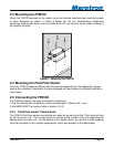
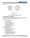
2.5.2 NMEA 2000
®
Connection
The NMEA 2000
®
connector can be found on the side of the enclosure. The NMEA 2000
®
connector is a round five pin male connector (see Figure 7). You connect the FFM100 to an
NMEA 2000
®
network using a Maretron NMEA 2000
®
cable (or an NMEA 2000
®
compatible
cable) by connecting the female end of the cable to the FFM100 (note the key on the male
connector and keyway on the female connector). Be sure the cable is connected securely and
that the collar on the cable connector is tightened firmly. Connect the other end of the cable
(male) to the NMEA 2000
®
network in the same manner. The FFM100 is designed such that
you can plug or unplug it from an NMEA 2000
®
network while the power to the network is
Page 10 Revision 1.2