


E-2
TROUBLESHOOTING
E-2
INVERTEC DC TIG STARTER
Observe all Safety Guidelines detailed throughout this manual
If for any reason you do not understand the test procedures or are unable to perform the tests/repairs safely, contact your
Local Lincoln Authorized Field Service Facility for technical troubleshooting assistance before you proceed.
CAUTION
PROBLEMS
(SYMPTOMS)
RECOMMENDED
COURSE OF ACTION
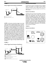
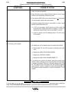
No output; fan does not operate. 1. Check that the input cable assembly is tightly connected.
2. Check the wiring at the 14-pin and 6-pin Amphenols. All connec-
tions should be insulated and free of debris.
3. Check that there is 42 VAC present between cavities “I” and “K”,
(leads 42 and 41), of the 14-pin Amphenol. If 42 VAC is present
between these cavities at the Invertec but not at the DC TIG
Starter, replace or repair the input cable assembly. If 42 VAC is
not present at the Invertec’s cavities, see the Instruction Manual
for the Invertec.
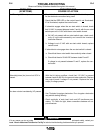
4. Check that 115 VAC is present between leads 41B and 215A. If
it is present, replace the fan and check that the outputs of the
auxiliary transformer are within 15% of nominal values: 380 VAC
between the U leads and 24 VAC between the Y leads.
5. Check that the GREEN LED on the control board is
illuminated.
If it is not illuminated, perform the following:
Check that 24 VAC is present between leads 101A and 102A
and between leads Y and Y. If 24 VAC is present between the Y
leads and not between leads 101A and 102A, check that all con-
nections on these wires are tight and have continuity. If all con-
nections are acceptable, replace the HIGH FREQ FIRING
BOARD.
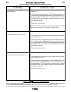
If 24 VAC is not present between the Y leads with plug J7 dis-
connected and 115 VAC present between 41B and 215A,
replace the auxiliary transformer, T1.
If 24 VAC is present between leads 101A and 102A, replace the
control board.
6. Replace the auxiliary transformer, T1.