


A-3
INSTALLATION
INVERTEC DC TIG STARTER
A-3
b. Keep the work and torch leads as short as possible
and as close together as possible. Lengths should
not exceed 25 ft. (7.6m). Tape the leads together
when practical.
c. Be sure the torch and work cable rubber coverings
are free of cuts and cracks that allow high frequen-
cy leakage.
d. Keep the torch in good repair and all connections
tight to reduce high frequency leakage.
NOTE: The DC TIG Starter’s frame is grounded to the
Invertec’s frame by the input cable assembly. The
input cable assembly must be kept in good repair and
all connections kept tight. The Invertec frame must be
grounded per the Invertec’s instruction manual.
e. When the machine is enclosed in a metal building,
several good earth driven electrical grounds around
the periphery of the building are recommended.
f. When the machine is in operation, keep all covers
securely fastened in place to minimize interference
radiation.
Failure to observe these recommended installation
procedures may cause radio or TV interference prob-
lems and may result in unsatisfactory performance.
Securing to Invertec
To secure the DC TIG Starter kit to the bottom of the
Invertec, refer to page F-4 at the back of this manual,
and :
a. Remove the bottom 4 wraparound screws from the
Invertec;
b. Place the Invertec on top of and inside the starter
kit’s case;
c. Align holes and reinsert the 4 screws.
Input Connection
An input cable assembly is supplied with the kit to
connect the DC TIG Starter to an Invertec. The cable
makes the connection between the 14-pin Amphenols
on the back of both the DC TIG Starter kit and the
Invertec. Refer to S20405 connection diagram at the
back of this manual.
Output Connection
An output cable assembly is supplied with the kit to
connect the DC TIG Starter with the Invertec’s nega-
tive or positive output quick connect terminals. (For
electrode negative or positive connections, with the
Invertec mounted on top of the DC TIG Starter). Refer
to S20405 connection diagram at the back of this
manual.
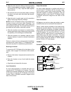
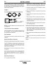
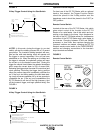
Torch Connection
All Magnum one and two piece gas-cooled or water-
cooled torches can be connected to the starter kit.
Figure 1 below shows connection of air-cooled torch-
es with the required adapters. One piece torches with
7/8-RH threads do not require an adapter, while one
piece torches with 3/8-RH threads require the 7/8-RH
to 3/8-RH adapter. The use of the 7/8-LH to 1/2” stud
adapter with one piece torches is recommended to
keep debris out of the water connection. Two piece
torches with 5/8-RH threads and a separate electrical
stud connector require the 5/8-RH to 7/8-RH adapter
and the 7/8-LH to 1/2” stud adapter.
FIGURE 1
Connection Diagram for Air-Cooled Torches.
DC TIG
STARTER
POWER / GAS
CONNECTION
7/8-RH
POWER / WATER
CONNECTION
7/8-LH
-OR-
-OR-
7/8 - RH POWER / GAS CONNECTION
AIR COOLED TORCH
AIR COOLED
TORCH
7/8 - RH TO 3/8 - RH ADAPTER
3/8 - RH POWER /
GAS CONNECTION
5/8 - RH CONNECTION
POWER LUG CONNECTION
7/8 - LH TO 1/2" STUD ADAPTER
DC TIG
STARTER
POWER / GAS
CONNECTION
7/8-RH
POWER / WATER
CONNECTION
7/8-LH
AIR COOLED
TORCH
7/8 - RH TO 5/8 - RH ADAPTER
7/8 - LH TO 1/2" STUD ADAPTER