


B-2
OPERATION
B-2
INVERTEC DC TIG STARTER
Power Source and Starter Kit Operation
Duty Cycle
The DC TIG Starter kit is rated to match the V300
Invertec’s duty cycle of 300 amps, 60% duty cycle,
and 250 amps, 100% duty cycle.
Invertec Control Function/Operation
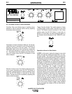
Power Switch:
Placing the Invertec’s power switch in
the “ON” position will energize the Invertec and the
DC TIG Starter kit. When the power is on, the digital
meter in the Invertec will activate and the fans in the
Invertec and the DC TIG Starter kit will operate.
OFF
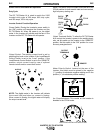
Output Control:
The welding current level is set by
adjusting this knob on the Invertec if the Local/Remote
Control Switch is set to the “Local” position. If the
Local/Remote Control Switch is set to the “REMOTE”
position, output current is set by use of optional
remote controls and/or current limit control.
NOTE: The digital meter in the Invertec will indicate
the current limit level when no current is flowing.
When current is flowing, the digital meter will display
the output current level.
OUTPUT
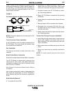
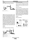
Mode:
This switch on the Invertec should be set to the
GTAW position for both scratch start and non-contact,
high frequency starting use.
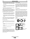
Output Terminals Switch:
To allow the DC TIG Starter
kit to control the Invertec’s power to the welding termi-
nals, set this switch on the Invertec to the “REMOTE”
position. Set this switch to the “ON” position for a con-
tinuously energized torch.
Meter Polarity Switch:
Located at the rear of the
Invertec, this switch must be placed in the negative
(“-”) position for electrode negative welding and in the
positive (“+”) for electrode positive welding.
Arc Force/Inductance:
This control on the Invertec is
disabled in the GTAW mode.
GMAW
FCAW
SMAW
CRISP
SMAW
SOFT
GTAW
OUTPUT
TERMINALS
ON
REMOTE
7
Has no effect when DC TIG Starter is used.