


If for any reason you do not understand the test procedures or are unable to perform the necessary
tests/repairs safely, contact your local authorized field service facility before you proceed.
This Troubleshooting Guide is designed to be used by the machine Owner/Operator.
Unauthorized repairs performed on this equipment may result in danger to the technician
and machine operator and will invalidate your factory warranty. For your safety, please
observe all safety notes and precautions detailed in the Safety Section of this manual to
avoid electrical shock or danger while troubleshooting this equipment.
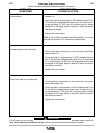
This Troubleshooting Guide is provided to
help you locate and repair possible machine
misadjustments. Simply follow the procedure
listed below.
Step 1. LOCATE PROBLEM (SYMPTOM)
Look under the column labeled “PROBLEM
(SYMPTOMS)”. This column describes
possible symptoms that your machine may
exhibit. Find the listing that best describes
the symptom that your machine is exhibiting.
Step 2. PERFORM RECOMMENDED
PROCEDURES
The second column labeled “RECOMMENDED
COURSE OF ACTION” lists the possibilities
that may contribute to the machine symptom.
Perform these tests/checks in the order
listed.
Step 3. CONSULT LOCAL AUTHORIZED
FIELD SERVICE FACILITY
If you have exhausted all of the
recommended tests in step 2, consult your
local Authorized Field Service Facility.
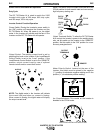
Visual Inspection
Clean interior of machine with a low pres-
sure airstream. Make a thorough inspection
of all components. Look for signs of over-
heating, broken leads or other obvious prob-
lems. Inspect all wiring, lugs, and connec-
tions to ensure that electrical connections
are tight and free of debris. All connectors
should make complete contact with their
mating components. All leads and lugs
should be fully inserted into their respective
connector cavities. Many problems can be
uncovered with a good visual inspection.
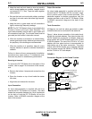
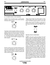
Open Circuit Voltage
The DC TIG Starter does not alter the open
circuit voltage of the Invertec. Consult the
Invertec’s manual for applicable open circuit
voltages. With the Invertec’s Output
Terminals Switch in the “ON” position, the
open circuit voltage should appear between
the Invertec’s positive output terminal and
both of the torch connection terminals of the
DC TIG Starter (for electrode negative con-
nections).
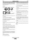
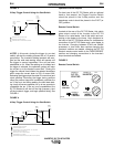
Test Conditions
Perform all powered tests with an isolated
42 VAC input supply such as from an
Invertec V300. Make ohmmeter checks only
after power has been disconnected from
machine.
Certain high voltage connections have been
insulated with RTV sealant. It is necessary
to break through the sealant with a sharp
probe in order to make voltage or resistance
checks on these connections. After the com-
pletion of all measurements and repair work,
all RTV punctures should be resealed with
RTV.
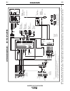
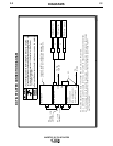
Refer to the DC TIG Starter’s wiring diagram
at the back of this manual for lead and con-
nector references listed.
WARNING
CAUTION
HOW TO USE TROUBLESHOOTING GUIDE AND GENERAL INFORMATION
ON TROUBLE SHOOTING
E-1
TROUBLESHOOTING
E-1
INVERTEC DC TIG STARTER