


B-4
OPERATION
B-4
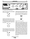
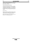
INVERTEC DC TIG STARTER
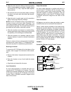
FIGURE 3
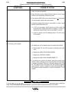
2-Step Trigger Control Using Arc Start Switch
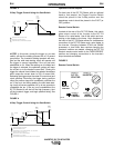
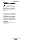
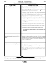
4-STEP: In this mode, closing the trigger (or arc start
switch) will start the welding process with a 0.5 second
gas preflow. The Invertec’s welding terminals will ener-
gize and the solid state starting circuit will operate until
the trigger is opened regardless if the arc has been
established or not. When the welding arc is initiated and
the trigger is released, the optimized upslope will ramp
the current up to the desired current limit. Closing the
trigger the second time initiates the selected downslope
which ramps the current down to 25% of current limit.
Releasing the trigger stops the crater fill current level and
starts postflow. Reclosing the trigger during postflow
skips the preflow stage and immediately restrikes the
arc. If the arc is lost during welding, the solid state start-
ing circuit will resume operation for up to two seconds to
re-establish the arc. If the arc is not re-established, the
DC TIG Starter kit will shut off the high frequency, shut
off the Invertec’s trigger, and begin postflow timing. See
FIGURE 4.
FIGURE 4
4-Step Trigger Control Using Arc Start Switch
35()/2:
3267)/2:
&855(17/,0,7&/
836/23(
$
$
%
67$57
6:,7&+
&/26('
67$57
6:,7&+
&/26('
75,**(5
75,**(538//(':,7+287*$6)/2:,1*
75,**(538//(''85,1*3267)/2:
$
$
%
75,**(55(/($6('72,1,7,$7(),1,6+,1*6(48(1&(
'2:16/23(2))
)$67
'2:16/23(21
35()/2:
3267)/2:
&855(17/,0,7&/
836/23(
$
$
%
&
'
'
67$57
6:,7&+
&/26('
67$57
6:,7&+
23(1('
67$57
6:,7&+
&/26('
67$57
6:,7&+
23(1('
75,**(5
75,**(538//(':,7+287*$6)/2:,1*
75,**(538//(''85,1*3267)/2:
75,**(55(/($6('7267$57:(/',1*352&('85(,)$5&+$'67$57('
75,**(538//('72,1,7,$7(),1,6+,1*6(48(1&(
75,**(55(/($6('726723&855(17
75,**(55(/($6(''85,1*'2:16/23(67236&855(17$1'67$5763267)/2:
$
$
%
&
'
'
3267)/2:67$576,)$5&','12767$57
'2:16/23(21
'2:16/23(2))
)$67
Operation with an Amptrol
For best use of the DC TIG Starter with an optional
hand or foot amptrol, the Trigger Function Switch
should be placed in the 2-step position and the
downslope control should be placed in the FAST (or
OFF) position.
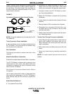
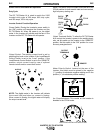
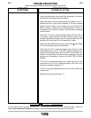
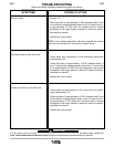
Remote Control Switch
Located at the rear of the DC TIG Starter, this switch
gives output control of the Invertec to the DC TIG
Starter or to a wire feeder. Use of this switch and con-
necting a wire feeder to the lower 14-pin Amphenol or
the back of the DC TIG Starter allows for simultaneous
connection of the DC TIG Starter and a wire feeder to
the Invertec. Changing between GTAW and GMAW
processes, or vise versa, then requires changing the
Invertec’s switches as needed, changing the DC TIG
Starter’s remote control switch to the “WIRE FEEDER”
position and changing connections to the Invertec’s
output terminals as needed.
FIGURE 5
Remote Control Switch
5(027(
&21752/
&21752/$7
&21752/$7
&211(&772
&211(&772
,19(57(&
'&7,*
67$57(5
)(('(5
:,5(
)(('(5
:,5(
723
%27720
6