


9
8/15/05
Manual No. 701-055M
Land Pride
Assembly Instructions for 4200/4400 ST & NT (S/N 418339+)
■
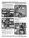
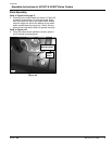
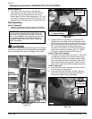
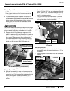
Refer to Figure 7B:
3. The Electric Bed Lift mounts in the same pin
connections as the Bed Latch Lock-Up Arm was
mounted. First mount the electrical end of the
Electric Bed Lift to the Treker frame with a 1/2" x 49/
64" clevis pin. Secure pin with 5/32" cotter pin. The
opposite end will be attached to the cargo box later.
Final Assembly
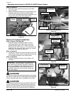
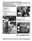
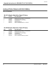
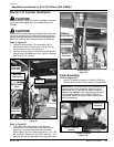
Refer to Figure 8B:
1. Locate T-shaped connector on Electric Lift Wiring
Harness and connect it to the electric lift connector.
!
CAUTION!
The cylinder needs to be extended to attach it to the cargo
box. Be very careful not to hit anything while extending the
cylinder causing bodily injury or damage to the vehicle.
Electric Bed Lift
Figure 7B
IMPORTANT: The Electric Bed Lift is protected by an
internal clutch in both directions. When the up or
down travel limit is reached, the electric dump will
make a loud “ratchet” noise indicating end of travel
limit has been reached or the Electric Bed Lift is
overloaded. When this noise is heard, release the
switch immediately.
21172
Electric Bed Lift
Electrical End
Electric Lift
Connector
T-Shape Connector
Figure 8B
2. Support electric lift cylinder up in alignment with
cargo box pin connection point and activate rocker
switch to extend electric lift cylinder until it is close to
its connecting point. With a secure grip on the cargo
box, remove its support and align cargo box pin
connection with electric lift cylinder mounting hole.
Attach the cylinder to cargo box with 1/2" x 49/64"
clevis pin and secure pin with 5/32" cotter pin.
Refer to Figure 5B on page 8:
3. Correctly orient rocker switch as shown in Figure 5B
on page 8 and activate it to raise and lower cargo
box. Pushing at the top of the rocker switch should
raise the cargo box and at the bottom of the rocker
switch should lower the cargo box. Switch the two
green wires if the switch does not operate correctly.
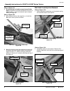
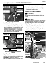
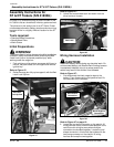
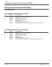
Refer to Figure 9B:
4. Once the rocker switch operates correctly, press it
into the dump mounting panel.
5. If the glove box was removed, reinstall it with the
drain holes located at the bottom by pushing the
existing rivets back into the dashboard.
Rocker Switch Plugged to Electrical Connector
Figure 9B
21175
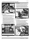
Electric Lift Wiring Harness
T-shape Connector
Electric Lift
Connector
21473
Rocker
Switch
Dump
Mounting Panel