


14
Manual No. 701-055M 8/15/05
Land Pride
Assembly Instructions for ST & NT Trekers (S/N 418338-)
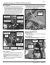
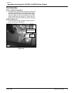
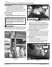
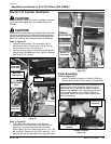
Refer to Figure 11C:
2. Locate the red and black leads on the electric lift
wiring harness. Also locate the main wiring harness
red and black leads that were disconnected from the
battery earlier. Bolt the red leads to the positive
battery post and then bolt the black leads to the
negative battery post.
!
CAUTION!
The cylinder needs to be extended to attach it to the cargo
box. Be very careful not to hit anything while extending the
cylinder causing bodily injury or damage to the vehicle.
3. Support electric lift cylinder up in alignment with
cargo box pin connection point and activate rocker
switch to extend electric lift cylinder until it is close to
its connecting point. With a secure grip on the cargo
box, remove its support and align cargo box pin
connection with electric lift cylinder mounting hole.
Attach the cylinder to cargo box with 1/2" x 49/64"
clevis pin and secure pin with 5/32" cotter pin.
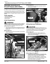
Red and Black Leads (NT Series Shown)
Figure 11C
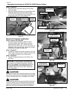
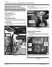
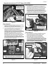
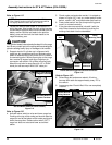
Refer to Figure 12C:
4. Activate rocker switch to raise and lower cargo box.
Pushing at the top of the rocker pad should raise the
cargo box and at the bottom of the rocker pad should
lower the cargo box. Rotate rocker switch 180
o
if
cargo box does not raise and lower as outlined
above.
NOTE: The pictures on this page are of an NT Series
Treker. Battery location and main wiring harness will be
in a slightly different location for the ST Series.
21177
Black Leads Bolted
to Negative Terminal
Red Leads Bolted to
Positive Terminal
5. Check rocker pad and make certain it is rotated as
shown in Figure 12C. If not, pry rocker pad off rocker
switch, rotate it 180
o
and press rocker pad back on.
6. Press rocker switch into the dump mounting panel
once it is oriented correctly.
7. If the glove box was removed, reinstall it with the
drain holes located at the bottom by pushing the
existing rivets back into the dashboard.
Rocker Switch Plugged to Electrical Connector
Figure 12C
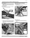
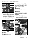
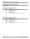
Refer to Figure 13C:
8. Raise cargo box and secure electric lift wiring
harness with cable ties approximately every 10" to
the vehicle.
9. Lower cargo box. Electric Bed Lift is now completely
installed.
Electric Bed Lift Wire Harness
Figure 13C
Rocker
Pad
Rocker
Switch
Electrical
Connector
Dump
Mounting Panel
21183
21181
Electric Bed Lift
Wiring Harness
Cable Ties
■