


8
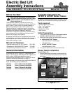
Manual No. 701-055M 8/15/05
Land Pride
Assembly Instructions for 4200/4400 ST & NT (S/N 418339+)
■
Electrical Wiring & Mounting Panels
Figure 4B
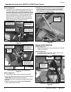
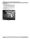
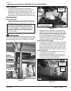
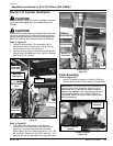
Refer to Figure 4B:
2. Locate behind the dashboard a green wire with red
connector, green wire with yellow stripe and red
connector and black wire with blue connector. Wires
can be located by looking through the left front fender
well at the dashboard. If unable to locate the wires,
then remove glove box by prying glove box from
dashboard with a screwdriver at its rivet locations.
Once the wires are located, pull them through the
dump mounting panel opening as shown.
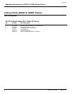
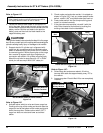
Rocker Switch with Electrical Wiring attached
Figure 5B
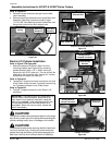
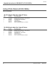
Refer to Figure 5B:
3. Plug wires to rocker switch terminals as follows:
• Green wire with yellow stripe and red connector labeled
Dump Down to rocker switch top terminal.
• Black wire with blue connector to middle rocker switch
terminal.
Dump Mounting
Panel Opening
21471
Black Wire With
Blue Connector
Green Wire With
Red Connector
Green Wire With
Yellow Stripe and
21472
Rocker Switch
This End Down
Green Wire With
Red Connector
Labeled Dump Up
Black Wire With
Blue Connector
Green Wire With
Yellow Stripe and
Red Connector
Labeled Dump down
Bottom Terminal
Top
Terminal
• Green wire with red connectorlabeled Dump Up to
rocker switch bottom terminal.
• Do not press rocker switch in to dump mounting panel
until after electric lift cylinder has been installed and
after correct wiring connections have been verified in
“Final Assembly” on page 9 step 3.
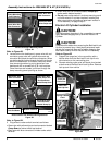
Electric Lift Cylinder Installation
!
CAUTION!
Securely support cargo box in the up position to prevent
injury while exchanging lock-up arm with Electric Lift
Cylinder.
!
CAUTION!
Care should be taken when removing the Bed Latch Lock-
Up Arm to prevent injury. Avoid pinch points and make
certain the cargo box does not fall when changing from
Bed Latch Lock-Up Arm to Electric Bed Lift Assembly.
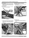
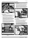
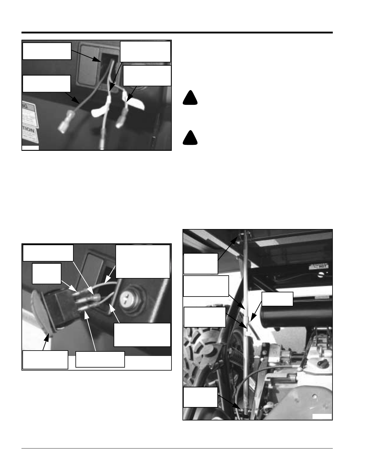
Refer to Figure 6B
1. Support the cargo box in the up position with a
device other than the Bed Latch Lock-Up Arm to
relive tension on the connecting pins.
2. Remove existing cotter pins and clevis pins located
at both ends of the Bed Latch Lock-Up Arm. Remove
lock-up arm from vehicle.
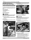
Rocker Switch Connection
Figure 6B
Cotter and
Clevis Pins
Bed Latch
Lock-Up Arm
Spring Loaded
Latch
Cotter and
Clevis Pins
Latch Pin
21173