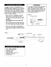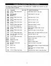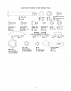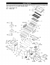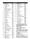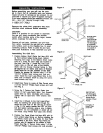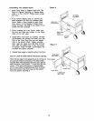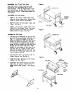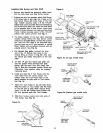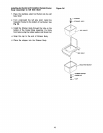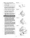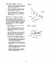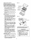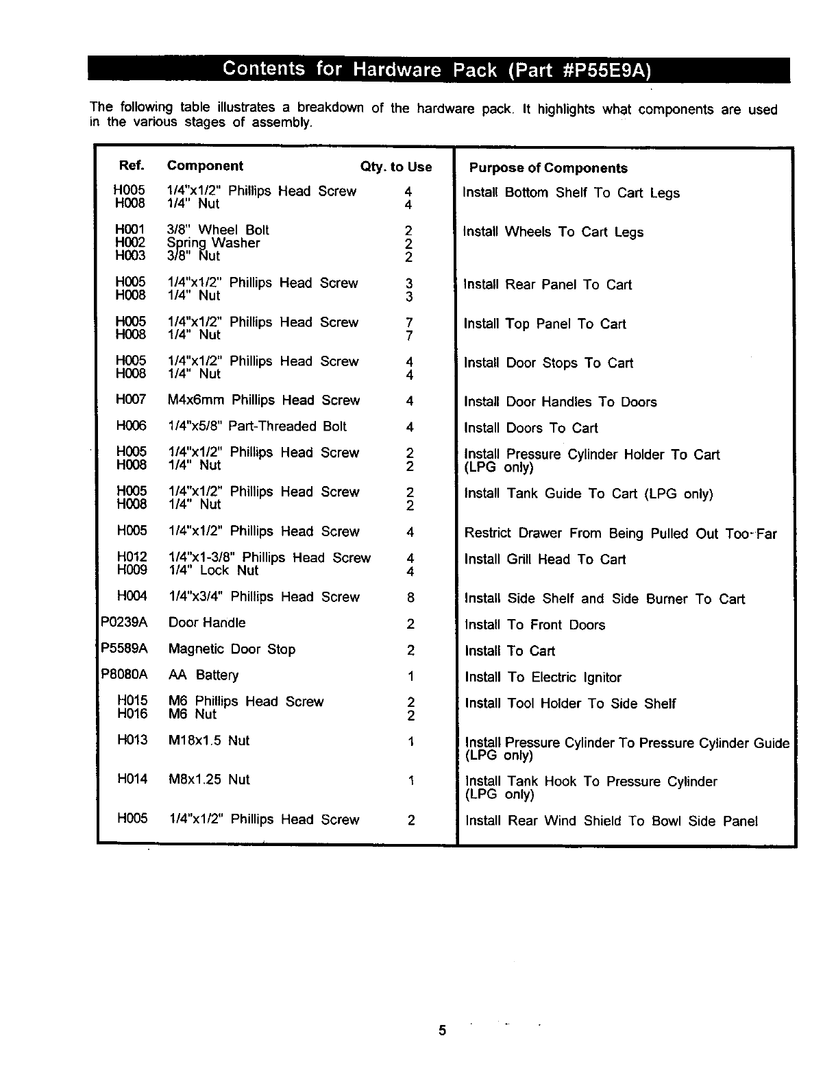
The following table illustrates a breakdown of the hardware pack. It highlights what components are used
in the various stages of assembly.
Ref. Component Qty. to Use
H005 1/4"x1/2" Phillips Head Screw 4
H008 1/4" Nut 4
H001 318" Wheel Bolt 2
H002 Spring Washer 2
H003 3/8" Nut 2
H005 1/4"x1/2" Phillips Head Screw 3
H008 1/4" Nut 3
H005 1/4"x1/2" Phillips Head Screw 7
H008 1/4" Nut 7
H005 1/4"x1/2" Phillips Head Screw 4
H008 1/4" Nut 4
H007 M4x6mm Phillips Head Screw 4
H006 1/4"x5/8" Part-Threaded Bolt 4
H005 1/4"x1/2" Phillips Head Screw 2
H008 1/4" Nut 2
H005 1/4"x1/2" Phillips Head Screw 2
H008 1/4" Nut 2
H005 1/4"x1/2" Phillips Head Screw 4
H012 1/4"xl-3/8" Phillips Head Screw 4
H009 1/4" Lock Nut 4
H004 1/4"x3/4" Phillips Head Screw 8
P0239A Door Handle 2
P5589A Magnetic Door Stop 2
P8080A AA BaKery 1
H015 M6 Phillips Head Screw 2
H016 M6 Nut 2
H013 M18x1.5 Nut 1
H014 M8x1.25 Nut
H005 1/4"x1/2" Phillips Head Screw
f
Purpose of Components
Install Bottom Shelf To Cart Legs
Install Wheels To Cart Legs
Install Rear Panel To Cart
Install Top Panel To Cart
Install Door Stops To Cart
Install Door Handles To Doors
Install Doors To Cart
Install Pressure Cylinder Holder To Cart
(LPG only)
Install Tank Guide To Cart (LPG only)
Restrict Drawer From Being Pulled Out Too-Far
Install Grill Head To Cart
J
i Install
Install
Install
Install
Install
Side Shelf and Side Burner To Cart
To Front Doors
To Cart
To Electric Ignitor
Tool Holder To Side Shelf
Install Pressure Cylinder To Pressure Cylinder Guide
(LPG only)
Install Tank Hook To Pressure Cylinder
LPG only)
Install Rear Wind Shield To Bowl Side Panel
5


